Multi-Axis Load Cells
Simultaneous force and moment measurement in 3-axis and 6-axis configurations. Custom solutions engineered for robotics, aerospace, automotive testing, and biomechanics applications.
Quick Overview
- Measure force in multiple directions simultaneously (3-axis or 6-axis)
- Typical configurations: Fx, Fy, Fz (forces) + Mx, My, Mz (moments/torques)
- Cross-talk specifications typically <1–2% for precision applications
- Multiple independent bridge outputs for simultaneous signal acquisition
- Custom integration available through Transcell engineering services
- Common applications: robotics, aerospace, crash testing, biomechanics research
What Are Multi-Axis Load Cells?
Multi-axis load cells are force measurement sensors designed to detect loads applied in multiple directions simultaneously. Unlike single-axis load cells that measure force in only one direction, multi-axis sensors incorporate multiple strain gauges arranged to isolate and measure components of force and torque along independent axes.
A typical 3-axis load cell measures linear forces along the X, Y, and Z axes (Fx, Fy, Fz). Six-axis sensors, also called force-torque (F/T) sensors, additionally measure rotational moments around those same axes (Mx, My, Mz). This dual capability makes them essential for complex industrial and research applications where force vectors act from unpredictable directions or where both linear and rotational forces must be monitored simultaneously.
Transcell specializes in custom sensor integration and can source or design multi-axis solutions tailored to your specific application requirements, load ranges, and environmental constraints. Whether you need a compact 3-axis configuration for robotic arm control or a full 6-axis system for aerospace payload testing, our engineering team can specify the right sensor and integrate it into your measurement system.
3-Axis vs. 6-Axis: Configuration Comparison
The choice between 3-axis and 6-axis load cells depends on your application’s measurement requirements. Below is a structured comparison:
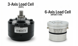
| Characteristic | 3-Axis Load Cell | 6-Axis Load Cell |
|---|---|---|
| Measured Components | Fx, Fy, Fz (linear forces only) | Fx, Fy, Fz + Mx, My, Mz (forces + moments) |
| Typical Applications | Weighing, platform load measurement, basic multi-directional force | Robotics, haptic feedback, torque measurement, aerospace testing |
| Complexity | Moderate; fewer independent bridge outputs | High; six independent measurement channels |
| Cost | Lower | Higher; more strain gauge elements and signal conditioning |
| Calibration | Straightforward cross-talk correction | Complex; requires full matrix calibration to isolate all components |
| Compact Design Feasibility | More feasible for miniature form factors | Requires careful design to avoid interference |
Common Applications for Multi-Axis Load Cells
Multi-axis sensors enable force measurement in dynamic, complex environments where traditional single-axis cells cannot provide adequate information.
Robotics & Collaborative Manufacturing
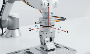
Six-axis force-torque sensors mounted at robot wrist or base points detect interaction forces during assembly, handling, and collaborative operations. Real-time feedback on Fx, Fy, Fz, Mx, My, Mz enables force control algorithms and collision detection, critical for safe human-robot collaboration. Typical resolution: sub-Newton forces, millinewton-meter torques.

Aerospace & Aerospace Component Testing
Aircraft structures undergo multi-directional loading during flight. Multi-axis load cells mounted on test fixtures measure combined wing lift, fuselage drag, control surface loads, and induced moments. Data validation during wind tunnel testing, flutter analysis, and certification testing rely on accurate 6-axis measurement. Environmental requirements often include high-temperature variants and aerospace-grade calibration documentation.
Automotive Crash & Impact Testing
Vehicle safety systems must understand forces during frontal, side, and rear impacts. Barrier load cells and seat belt restraint sensors employ multi-axis measurement to quantify impact severity, restraint effectiveness, and structural deformation. Real-time data guides airbag deployment algorithms and post-crash analysis. Specifications include high transient performance and rapid sampling rates (1–5 kHz).
Biomechanics & Gait Analysis Research
Force plates and wearable sensor systems measure ground reaction forces during human locomotion. Multi-axis cells capture vertical (Fz) and shear (Fx, Fy) forces, enabling calculation of center of pressure, stride mechanics, and muscle load distribution. Clinical and sports applications require high sensitivity, low noise, and stable long-term calibration.
CNC Machine Tool Monitoring
Cutting forces during machining include thrust (axial), radial, and tangential components. Multi-axis spindle load cells or dynamometer systems measure all three simultaneously to optimize tool life, detect tool breakage, and maintain process stability. Typical ranges: 0–5 kN per axis with response bandwidth of 2–10 kHz.
Wind Tunnel & Aerodynamic Testing
Aircraft models and components suspended in wind tunnels require full 6-axis measurement to capture lift, drag, side force, roll, pitch, and yaw moments. Strain-gauge load cells mounted on the support sting isolate aerodynamic loads from structural interference. Calibration matrices correct for sting compliance and load cell cross-talk.
How Multi-Axis Load Cells Work
Multi-axis sensors employ strategically positioned strain gauge bridges to isolate force and moment components. Here’s the fundamental operating principle:
Strain Gauge Arrangement
In a 3-axis load cell, strain gauges are mounted on elastic elements (beams, rings, or columns) oriented along the X, Y, and Z axes. When a force is applied, the corresponding elastic element deflects, causing strain gauge resistance changes. Each axis typically has its own bridge circuit, allowing independent measurement of Fx, Fy, and Fz.
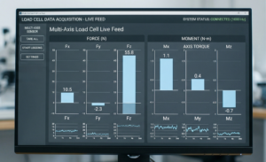
Bridge Output Signals
Each axis produces a voltage output proportional to applied force. A 6-axis sensor generates six independent voltage signals—one for each force and moment component. Signal conditioning amplifiers convert these analog voltages into digital values or proportional 4–20 mA outputs suitable for data acquisition systems and industrial controllers.
Cross-Talk Correction
Perfect axial isolation is impossible; forces on one axis inevitably produce small signals on adjacent axes (cross-talk). Modern multi-axis sensors limit cross-talk to 1–2% through careful mechanical design and electronic compensation. High-precision applications may employ calibration matrices to further reduce residual coupling. Transcell works with sensor manufacturers to ensure your system meets cross-talk specifications.
Integration with Control Systems
Multi-axis data feeds directly into control algorithms, haptic feedback systems, or data acquisition platforms. Robot controllers use real-time 6-axis force data for impedance control and collision avoidance. Aerospace test systems log and analyze multi-axis data for flight envelope validation and structural durability assessment.
Selection Considerations for Multi-Axis Load Cells
Choosing the right multi-axis sensor requires evaluation of multiple technical and operational factors. Consider these key criteria:
Load Range
Define maximum expected forces and moments on each axis. Overload capacity is critical; sensors rated too low will fail, while oversized sensors sacrifice resolution. Specify minimum and maximum loads for each component.
Accuracy & Repeatability
Industrial applications typically require ±0.5–2% full-scale accuracy. Aerospace and research applications may demand ±0.1–0.3%. Repeatability ensures consistent measurement across many loading cycles.
Cross-Talk Specifications
Cross-talk <1% is excellent for most applications. Robotics and biomechanics research may accept up to 2%. Verify cross-talk across your expected load range—values often worsen near overload.
Environmental Conditions
Temperature stability, humidity, vibration, and shock resistance all impact sensor longevity. Aerospace sensors endure extreme thermal cycling; manufacturing floor sensors face coolant exposure. Specify your environment early.
Output Format
Analog (4–20 mA, 0–10 V), digital (RS-232, CAN), or amplified voltage outputs suit different integration strategies. Robotics systems often prefer direct 6-channel analog; aerospace testing may require industry-standard data recorders.
Form Factor & Integration
Mounting location, available space, and alignment tolerances drive sensor selection. Miniature sensors exist for tight spaces; larger sensors offer better isolation and lower cost. Custom mounting brackets and cable routing affect installation success.
Integration with Transcell Products & Services
Transcell does not currently manufacture multi-axis load cells as off-the-shelf products, but we specialize in sourcing, integrating, and validating custom multi-axis solutions tailored to your application. Here’s how our expertise supports your project:
Custom Engineering Design
Our engineering team evaluates your application requirements and recommends the appropriate multi-axis sensor configuration. We assess whether 3-axis or 6-axis measurement is necessary, specify load ranges and accuracy targets, and develop integration schematics that minimize environmental interference and maximize signal fidelity.
Sensor Integration & Calibration
We source multi-axis sensors from leading manufacturers—including Interface, HBM/HBK, Kistler, and ATI Industrial Automation—and integrate them into complete weighing or measurement systems. We establish proper grounding, shielding, and signal routing; perform factory calibration with traceable documentation; and deliver calibration matrices for cross-talk compensation if required.
Cross-Reference with Existing Transcell Products
Many multi-axis applications benefit from complementary Transcell components:
- Miniature Load Cells: When space is critical, our miniature single-axis compression and tension cells provide building blocks for custom multi-axis arrays or can serve as validation sensors in your testing rig.
- Compression Load Cells: Multi-axis measurement often requires precise base reference loads. Our compression cells provide stable, repeatable baselines and are frequently used in conjunction with custom 3-axis systems.
- Button Load Cells: Compact point-contact measurement at multiple points can approximate multi-axis behavior. We’ve engineered multi-button arrays for distributed load measurement in aerospace test fixtures.
- Indicators & Controllers: Our signal conditioning units can acquire, filter, and display data from multiple sensor channels. Custom programming enables real-time cross-talk correction and composite force/moment calculations.
System Validation & Testing
Before deployment, multi-axis systems require functional validation. We conduct load linearity testing, cross-talk verification, thermal stability checks, and environmental stress testing (vibration, humidity, temperature cycling). Our test data provides confidence for mission-critical applications.
Need a Custom Multi-Axis Solution?
Our engineering team is equipped to specify, source, integrate, and validate multi-axis load cell systems for your application.
Contact us to discuss your requirements—load ranges, environmental conditions, integration timeline, and budget constraints.
sales@transcell.com
Complement Multi-Axis Measurement with Standard Load Cells
Although multi-axis sensors provide comprehensive force measurement, many applications integrate single-axis Transcell load cells for redundancy, validation, or specialized sub-system measurement. Consider these related products:
Frequently Asked Questions
Ready to Specify Your Multi-Axis Solution?
Contact Transcell’s engineering team to discuss your application, load requirements, and integration timeline. We’ll guide you through sensor selection, system design, and field validation.
Engineering Support & Resources
Transcell is committed to providing expert guidance beyond product supply. Our services include:
- Custom Engineering Design — Load cell selection, system architecture, integration planning
- Technical Services — System integration, calibration, troubleshooting, and support
- Request a Quote — Multi-axis sensor sourcing and custom system pricing
- Datasheets & Documentation — Technical specifications, calibration guides, and application notes
We ship from Buffalo Grove, IL, and our team is available to support your project from concept through deployment and beyond.