Product Description

Signal Conditioner • DIN-Rail Mount • Signal Link

Multi-Function Signal Conditioner for Load Cells and Force Sensors

The Signal Link is a compact, DIN-rail signal conditioner that converts mV/V strain-gauge signals into standardized analog, digital, and relay outputs for industrial measurement and control. A single unit replaces a stack of discrete amplifiers, isolators, and transmitters: five scalable analog output ranges, MODBUS-RTU over RS-485 or USB-C, and three programmable relays for setpoint and alarm control.

Built around the high-speed AD-09 converter with selectable sampling from 10 to 7,200 Hz and resolution of approximately 400,000 counts at 3 mV/V, the Signal Link delivers laboratory-grade precision in a 1.0 in wide panel-ready enclosure. It accepts up to eight 350 ohm load cells over 4-wire or 6-wire sensing and snaps tool-free onto any standard 35 mm DIN rail. Everything is configurable from the front panel with no laptop required.

System-level Cal PLC calibration trims the entire signal chain end-to-end across five reference points, so what the load cell senses is exactly what the PLC reads. Backed by a 12-month warranty, with US-based support from Transcell's facility in Buffalo Grove, IL since 1981.

7,200 Hz
Max Sampling Rate
AD-09 high-speed converter

400K cts
Resolution
@ 3 mV/V input

8 cells
Load Cell Capacity
Up to 8 × 350 Ω

4 outputs
Analog Output Types
0-10V, ±10V, 4-20mA, ±20mA

1.0 in
Panel Width
35 mm DIN rail, tool-free

One Conditioner, Every Output

Signal Link signal conditioner side view showing all terminal connections
01

Universal Analog Output

Four field-selectable output modes: 0-10 V, ±10 V, 4-20 mA, and ±20 mA. User-defined force scaling with ±0.03% FS accuracy into a 1 kΩ load. Drives PLCs, indicators, DCS, and SCADA directly.

Signal Link signal conditioner top and bottom terminal connections
02

Dual Digital Communication

RS-485 half-duplex MODBUS-RTU daisy-chains up to 32 nodes on a single addressable bus. USB-C carries VCP for PC configuration and firmware updates. Both ports transmit continuous and demand ASCII formats simultaneously.

Signal Link front panel OLED display showing gross weight homescreen
03

Three Programmable Relays

Three normally-open Form-A relays switch up to 250 VAC / 30 VDC at 5 A (150 W) each. One isolated optocoupled input triggers manual operations. Four built-in process modes: Auto Fill, Manual Fill, Check-Weight, and Pass-Band.

Signal Link front panel OLED display showing 4-20mA analog output mode
04

System-Level Cal PLC Calibration

Cal PLC steps the live analog output through five fixed reference levels at 0, 25, 50, 75, and 100% of range. Trim the connected PLC, indicator, or DCS at each point so the entire measurement chain is calibrated end-to-end, not just the sensor stage.

Every Capability, On Board

High-Speed Acquisition: 10 to 7,200 Hz
The AD-09 converter with 5 V square-wave excitation samples at selectable rates up to 7,200 Hz, resolving approximately 400,000 counts at 3 mV/V. Rated input range is ±4.5 mV/V with a maximum of ±7.8 mV/V.

Smart Filtering and Stability
Layered digital filtering: simple moving average (1 to 8 samples), autoranging filter (32, 48, or 64 samples), auto-engaged FIR at 10 and 20 Hz, and zero tracking (0 to 0.002 mV/V window) keep readings rock-steady under vibration and dynamic loads.

White OLED Display, 6 Digits
64 × 48 dot-matrix white OLED shows up to six digits plus unit glyphs (lb, kg, g, kN, t) and status annunciators for center-of-zero, net/gross, and stability. Three tri-color status LEDs mirror relay outputs OUT1, OUT2, and OUT3.

Front Panel Configuration: No Laptop Required
Four-key navigation (DISPLAY, MENU, SELECT/TARE, EXIT) accesses six on-device menus: Measure, Cal Setup, V/mA Out, Dig Comm, Relay IO, and System. All parameters set directly on the device. Scan the front-panel QR code for quick access to manuals.

±5-Point Linearization
Positive and negative linearization up to five points each corrects non-linear sensor response across the full operating range. Combined with Key-In span calibration and live calibration modes for flexible commissioning in the field.

32-Node MODBUS-RTU Network
RS-485 half-duplex bus daisy-chains up to 32 Signal Link units on a single addressable line. Supports MODBUS-RTU 16/32 bit and ASCII PRT/PT2/PT5 formats at 2,400 to 57,600 baud. Fit a 120 ohm terminator at each end node.

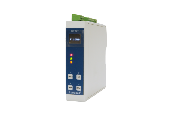
Read It. Set It. On the Rail.

A white dot-matrix OLED and a four-key pad put live readings and the full six-menu configuration system on the front of the device, visible and adjustable without disconnecting from the panel.

Signal Link home screen showing gross weight display
Home
Gross Weight

Signal Link measure menu run-mode display
Measure
Run-Mode Menu

Signal Link signal type output configuration menu
Sig Type
Output Config

Signal Link 4-20mA analog output mode display
4-20 mA
Analog Mode

White OLED, 6 Digits
64 × 48 dot-matrix display with unit glyphs (lb, kg, g, kN, t) and status symbols for center-of-zero, net/gross, and stability. Selectable decimal placement and count-by (1, 2, or 5).

Tri-Color Status LEDs
Red, green, and orange LEDs mirror relay outputs OUT1, OUT2, and OUT3, giving operators at-a-glance process state from across the panel without reading the display.

Four-Key Navigation
DISPLAY, MENU, SELECT/TARE, and EXIT walk through all six on-device menus: Measure, Cal Setup, V/mA Out, Dig Comm, Relay IO, and System. Password lock-out available.

Four Built-In Relay Control Modes

The Relay IO menu continuously compares gross or net weight against preset setpoints to drive three relay outputs, enabling dosing, check-weighing, sorting, and alarms directly on the device, with or without a PLC.
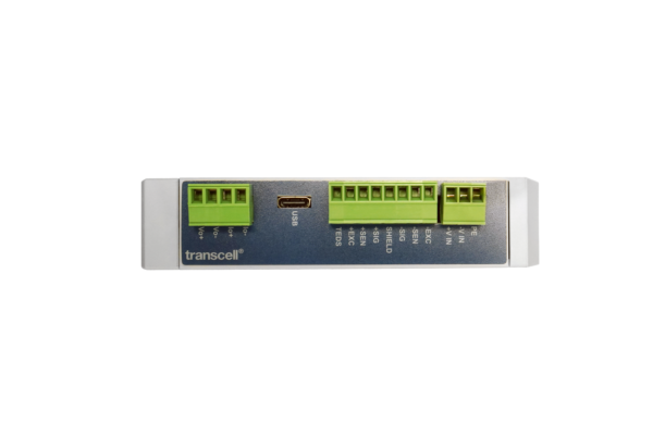
Mode 01
Auto Fill
Three sequential setpoints gate coarse, medium, and fine feed. Relays re-activate automatically if weight falls back.

Mode 02
Manual Fill
Same staged logic as Auto Fill, triggered from the control input and measured as the change from start weight. Outputs latch and hold.

Mode 03
Check-Weight
Classifies each load against Low, High, and Ex-High limits. Fires distinct relays for under-weight, accept, over, and reject on grading lines.

Mode 04
Pass Band
Simple in-tolerance window defined by Low and High setpoints. Green LED confirms when the measured weight sits inside the accepted band.

Every Port, Mapped

Signal Link signal conditioner side view showing all terminal connections

All field wiring lands on color-keyed, detachable screw-terminal blocks split across the top and bottom sides of the module. The USB-C port is the only non-removable connector. A flat-blade tool is supplied.

Top Edge
Analog OutVo+, Vo-, Io+, Io-
USBType-C (VCP + firmware)
Load CellTEDS, ±EXC, ±SEN, ±SIG, SHIELD
Power+VIN, -VIN, PE (DC 12-30 V)

Bottom Edge
RS-485AA, BB, AA, BB (daisy-chain)
Trigger InputIN_V+, IN_V- (10-30 VDC, opto)
Relay OUT1250 VAC / 30 VDC, 5 A (red LED)
Relay OUT2250 VAC / 30 VDC, 5 A (green LED)
Relay OUT3250 VAC / 30 VDC, 5 A (orange LED)
OUT_COMCommon return for OUT1-OUT3

Common Applications

Filling & Batching

Hopper & Tank Weighing

Electronic Belt Scales

Check-Weighing & Sorting

PLC / SCADA Integration

Force & Press Monitoring

Material Dosing

Test Stands & R&D

Key Specifications

Specification Signal Link
A/D Converter AD-09 High-Speed
Sampling Rate 10 to 7,200 Hz (selectable)
Resolution ~400,000 counts @ 3 mV/V
Input Signal Range ±4.5 mV/V rated, ±7.8 mV/V max
Excitation 5 V square wave
Load Cell Capacity Up to 8 × 350 Ω (4/6-wire, TEDS-ready)
Analog Output Types 0-10 V, ±10 V, 4-20 mA, ±20 mA
Analog Accuracy ±0.03% FS @ 20°C
Analog Nonlinearity ±0.002% FS
Digital Communication RS-485 (MODBUS-RTU) + USB-C (VCP)
Network Nodes Up to 32 daisy-chain
Relay Outputs 3 × Form-A, NO, 250 VAC / 30 VDC, 5 A
Trigger Input 1 opto-isolated, 10-30 VDC, 12 mA max
Display 64 × 48 white OLED, 6 digits, 3 LEDs
Power Supply DC 12-30 V ±10%, ≤ 4 W, 500 mA max
Operating Temperature -30 to +60°C (compensated -10 to +40°C)
Protection Rating IP20
Enclosure PA, UL 94 V-0
Dimensions (H × W × D) 3.9 in × 1.0 in × 4.6 in (100 × 25 × 117 mm)
DIN Rail 35 mm standard, tool-free snap mount
Warranty 12 months limited

Laboratory-Grade Accuracy
±0.03% FS analog output accuracy. ±0.001% FS digital nonlinearity. AD-09 high-speed converter with approximately 400,000 count resolution at 3 mV/V.

Panel-Ready Form Factor
1.0 in wide, tool-free snap mount onto standard 35 mm DIN rail. Detachable screw terminals. Stacks shoulder-to-shoulder. No fasteners required.

12-Month Warranty
12 months limited warranty. US-based support from Transcell's facility in Buffalo Grove, IL since 1981.

Category:

Dimensions / 3D Drawings

Note: You may need a software that can open/view STEP files.

Interchangeable

Ask us about our OEM and Dealer Pricing

Contact Us
Close-up view of clevis joint

Insights

Accurate and Reliable Force Feedback Using Load Pins

Read More

Industries

Experience to Solve Your Problems

Proven product quality and performance combine with our engineering experience to solve force measurement challenges in any industry that needs load cells and related force sensing equipment.