Load Cells: How They Work, Types, Selection Matrix & Glossary | Transcell
Transcell Technology Inc. • Industrial Weighing & Force Measurement
Load Cells: How They Work, Types, Applications & How to Choose the Right Sensor
Built for U.S. B2B teams—OEMs, engineers, integrators, and purchasing managers—who need stable, repeatable force and weight measurement in real industrial environments.
Technical Review: Transcell Calibration & Metrology Specialists
What you’ll get: fundamentals + practical selection, mounting, signal integrity, calibration, and failure-mode guidance.
What Is a Load Cell?
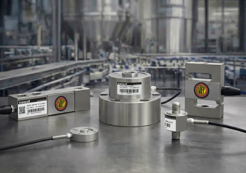
A load cell is a transducer that converts mechanical force (weight, tension, compression, shear, or bending)
into a measurable electrical signal. Most industrial load cells use strain gauges bonded to an elastic metal element.
As force is applied, microscopic deformation changes gauge resistance; a Wheatstone bridge converts that change into a proportional output,
commonly specified as mV/V.
Load cells are used in industrial weighing, automation, packaging, robotics, test & measurement, tank/hopper systems, conveyors, and OEM equipment where
accuracy and long-term stability matter as much as speed.
Need parts now? Browse load cells or shop indicators & signal conditioning.
1) What Does a Load Cell Do?
A load cell is a sensor that measures force by converting it into an electrical output that can be displayed, transmitted, or recorded.
In industrial environments, load cells are commonly used to measure weight (gravity-based force) or process force
(tension/compression in machinery and test systems).
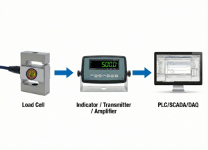
A key point for engineers: a load cell is only one component in the measurement chain. System performance depends on:
(1) the sensor, (2) the mechanical load path (mounts/fixtures), and (3) the electrical interface
(indicator, transmitter, PLC module, DAQ).
That’s why “good specs on paper” can still produce unstable readings if mounting or signal integrity is poor.
If you want a fast starting point: pick a load cell family, then match the electronics (indicator/conditioner/transmitter) to your control system.
2) How Load Cells Work (Engineering Explanation)
The most common industrial technology is the strain-gauge load cell. It uses a machined metal element designed to deform by a tiny,
controlled amount under load. That micro-strain is measured using bonded strain gauges and converted into an electrical signal.
2.1 Elastic Deformation: The Physics That Makes Load Cells Accurate
Load cells are engineered to operate in the material’s elastic region, meaning the sensing element returns to its original shape when the load is removed.
In the elastic region, the relationship between force and strain remains predictable and (in a properly designed load cell) highly linear.
If a load cell is overloaded, shock-loaded, or exposed to harmful side forces, the sensing element can enter plastic deformation (permanent change),
resulting in offset drift, non-linearity, or failure. Correct capacity selection and proper mounting are the best defenses.
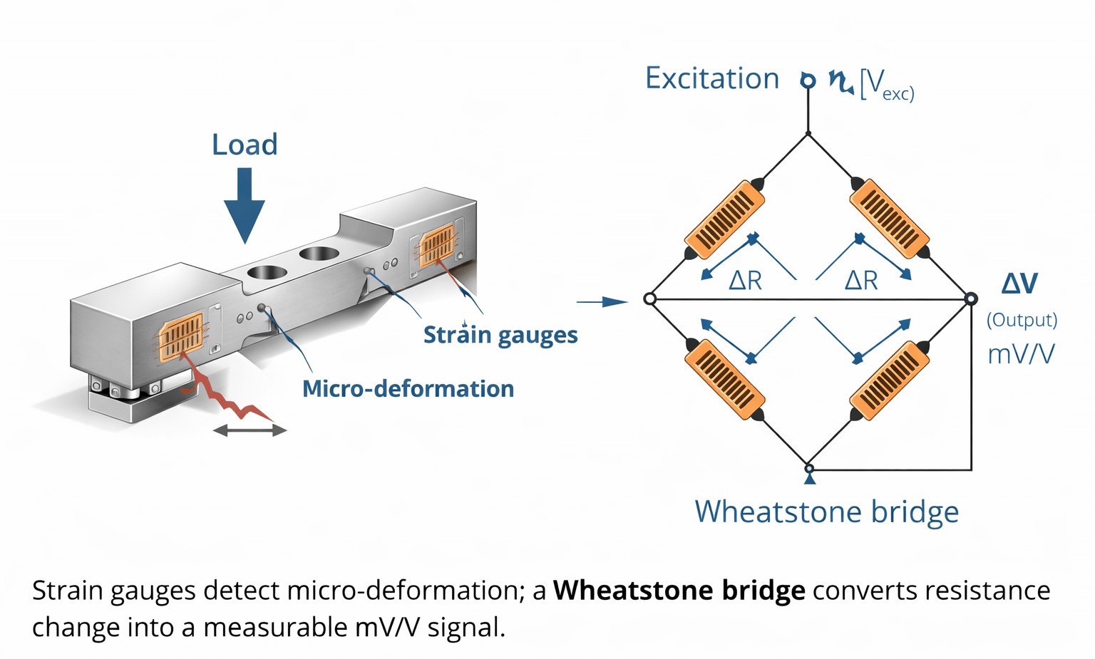
2.2 Strain Gauges: Converting Strain into Resistance Change
A strain gauge is a resistive element that changes electrical resistance when stretched or compressed.
In a load cell, gauges are bonded at locations that experience predictable tensile and compressive strain under load.
Even tiny deformation (often microns) is enough to produce a measurable resistance change.
2.3 Wheatstone Bridge: Why Load Cells Output mV/V
Strain-gauge load cells typically use a Wheatstone bridge (often four active gauges).
As force is applied, the bridge becomes unbalanced and produces a small differential voltage output.
Because the signal is small, it’s specified as mV/V (millivolts output per volt of excitation).
- Excitation: a stable input voltage supplied to the bridge (commonly 5–10V DC).
- Output: a proportional mV/V signal that is amplified/conditioned for display, control, or logging.
2.4 From Sensor to System: How mV/V Becomes Weight or Force
- Force is applied (compression, tension, shear, or bending).
- The sensing element deforms elastically.
- Strain gauges change resistance proportionally.
- The Wheatstone bridge produces a proportional mV/V output.
- Electronics convert the signal into engineering units (lbs/kg/N) or industrial outputs (4–20mA, 0–10V, Modbus, etc.).
2.5 Why Real-World Accuracy Depends on Mechanics (Not Just the Datasheet)
Field performance is strongly influenced by load introduction, mounting alignment, side-load control, temperature, vibration, moisture, EMI, grounding, and cable routing.
In other words, a high-accuracy load cell can still produce poor results if the installation is mechanically or electrically compromised.
3) Types of Load Cells (and When to Use Each)
Load cells are often grouped by shape (shear beam, S-type, pancake), but the most reliable selection approach is to identify:
(1) load direction, (2) mounting constraints, and (3) how well the design rejects unwanted forces like side load, torque, and vibration.
See all Transcell load cell families.
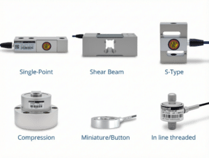
3.1 Single-Point Load Cells
Best for: bench/platform scales, checkweighers, packaging lines, compact machines.
Single-point load cells maintain accuracy even when the load isn’t perfectly centered (within a rated platform size).
Browse single-point load cells.
3.2 Shear Beam & Double-Ended Shear Beam
Best for: floor scales, industrial platforms, tank/hopper weighing, batching systems, conveyors.
Shear beam styles are widely used due to stability and rugged real-world performance.
Start here: single-ended beams or double-ended beams.
3.3 S-Type (S-Beam) Load Cells
Best for: hanging scales, tensile testing, suspended loads, in-line force measurement, industrial retrofits.
S-type load cells are versatile for tension and compression.
Browse S-beam load cells.
3.4 Compression Load Cells (Canister / Column / Pancake)
Best for: truck scales/weighbridges, silos/tanks, heavy industrial loads, test stands.
Compression styles support high capacities; pancake designs fit low-profile installations.
Browse pancake load cells.
3.5 Miniature & Button Load Cells
Best for: robotics tooling, medical devices, automation fixtures, laboratory equipment.
Miniature sensors fit constrained spaces; load introduction and flatness matter.
Browse miniature/button load cells.
3.6 Multi-Axis Force Sensors (3-Axis / 6-Axis)
Best for: robotics, aerospace/automotive R&D, complex force/torque measurement.
Multi-axis sensors are often engineered as OEM projects. Talk to an engineer.
3.7 Digital & Wireless Load Cells
Best for: long cable runs, high-noise environments, networked diagnostics, difficult cabling.
Digital systems can improve noise immunity and diagnostics depending on the architecture.
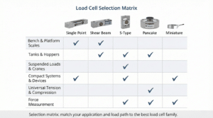
4) Load Cell Selection Matrix (Fast)
Use this matrix to quickly narrow down the best starting point. Final selection should confirm mounting, environment, output format, and accuracy requirements.
| Application | Typical Load Cell Type | Common Output | Notes / Watch-outs |
|---|---|---|---|
| Bench / small platform scales | Single-point | mV/V | Platform stiffness + off-center behavior matters |
| Floor scales / pallet scales | Beam load cells (often 4-cell) | mV/V | Junction box trimming + consistent cabling improves repeatability |
| Tanks / hoppers / silos | Weighing modules | mV/V or 4–20mA | Piping forces & thermal expansion can cause drift |
| Suspended loads / hanging systems | S-type (tension) | mV/V | Use alignment hardware to prevent side loads |
| Heavy capacity / low profile | Pancake compression | mV/V | Confirm load button / load introduction method |
| Robotics tooling / compact fixtures | Miniature/button | mV/V | Mount flatness and eccentric load control are critical |
| PLC-only monitoring (simple) | Any + transmitter | 4–20mA / 0–10V | Great for trends/thresholds; may reduce precision vs indicator |
| High-noise or long cable runs | Digital or remote conditioning | Modbus/RS485 | Noise immunity improves; verify system compatibility |
5) Load Cell Applications by Industry
Load cells are used wherever weight or force must be measured reliably—especially when instability causes rejects, rework, downtime, safety issues, or compliance risk.
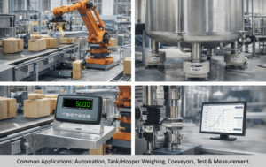
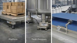
5.1 Industrial Automation & Packaging
- Filling/packaging lines and checkweighing
- Conveyor weighing and process verification
- Press-fit monitoring and assembly validation
- Quality control and reject automation
5.2 Process Weighing (Tanks, Hoppers, Batching)
- Ingredient batching and mixing systems
- Tank/hopper monitoring by weight
- Bulk material dosing and loss-in-weight control
For faster installs and better load-path control, weighing modules are a strong starting point.
5.3 Agriculture & Livestock
- Livestock weighing and herd management
- Feed batching and grain storage monitoring
- Outdoor/dirty environments where sealing matters
5.4 Food & Beverage
- Washdown environments requiring corrosion resistance
- Portioning, batching, checkweighing, QA/QC
5.5 Test & Measurement / R&D
- Material/component testing
- Production test stands and QA fixtures
- Robotics force measurement and feedback systems
6) How to Choose the Right Load Cell (Engineer’s Checklist + Examples)
6.1 Define Force Direction and the Load Path
Start with how force enters the sensor (compression/tension/shear/bending) and confirm you can control side load, torque, and misalignment through the mounting design.
6.2 Choose Capacity Correctly (Avoid Oversizing)
Oversizing capacity “for safety” can reduce sensitivity and resolution. A common guideline is 125–150% of maximum expected load,
then add mechanical overload protection if shock loads are possible.
6.3 Environment & Protection Requirements
- Temperature: affects zero and span stability
- Washdown/humidity: choose appropriate sealing and corrosion-resistant materials
- Vibration: improve mounting rigidity and apply appropriate filtering
- Electrical noise: plan shielding, grounding, and cable routing
6.4 Output & Controls Compatibility
- mV/V: precision weighing with indicators/conditioners
- 4–20mA / 0–10V: straightforward PLC integration
- Digital (Modbus/RS485, etc.): better noise immunity + diagnostics
- Wireless: when cabling is impractical
6.5 Common “Right Answers” (Fast Mapping)
- Floor/platform scales: beam load cells (often 4-cell)
- Tanks/hoppers: weighing modules or compression + proper mounts
- Suspended loads: S-type (tension)
- Low profile heavy load: pancake compression
- Small-space tooling: miniature/button or inline threaded
7) Output Signals (mV/V, 4–20mA, 0–10V, Digital, Wireless)
The best output format depends on distance, noise environment, architecture (PLC vs indicator), and diagnostics requirements.
7.1 mV/V (Bridge Output)
Standard strain-gauge output is low-level mV/V. It’s highly precise but requires proper excitation, amplification, filtering, and grounding.
7.2 Analog Outputs (4–20mA / 0–10V)
Common for controls and trend monitoring. Useful when a PLC needs stable engineering units via an analog input and the installer wants a simpler wiring model.
7.3 Digital Outputs (RS485/Modbus, CANbus, etc.)
Digital systems can improve noise immunity and support multi-drop networks and diagnostics, depending on implementation.
7.4 Wireless
Wireless can work well for temporary installs or difficult cabling, but must be engineered for power, range, and interference resilience.
8) Wiring, Signal Conditioning & PLC Integration
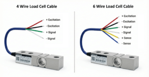
Common wiring: 4-wire (Excitation+/-, Signal+/-) vs 6-wire (adds Sense+/- to compensate voltage drop).
8.1 Typical Load Cell Wiring (4-Wire vs 6-Wire)
Many load cells use 4-wire wiring (Excitation+/-, Signal+/-). Higher-performance systems often use 6-wire wiring that adds Sense+/-
to compensate for voltage drop in longer cables.
8.2 What Signal Conditioning Does
- Amplifies low-level mV/V into usable engineering signals
- Filters vibration/noise to stabilize readings
- Enables scaling, linearization, and diagnostics
- Provides outputs such as 4–20mA, 0–10V, or digital protocols
8.3 PLC Integration Patterns
- Best accuracy: mV/V → conditioner/indicator → digital to PLC
- Simple controls: load cell + transmitter (4–20mA / 0–10V) → PLC analog input
- Networked: digital conditioning module via Modbus/RS485
9) Mounting, Load Introduction & Best Practices
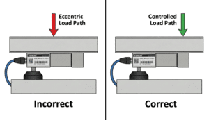
Mounting matters: uncontrolled side load and torque are common causes of drift and premature failure.
9.1 Control the Load Path
- Use flat, rigid mounting surfaces
- Prevent side loads, torque, and twisting
- Use alignment hardware in tension systems
- Add mechanical stops if overload/shock is possible
9.2 Cable Routing and EMI Control
- Keep signal cables away from motor power/VFD lines
- Avoid tight coils and sharp bends
- Maintain shielding/ground continuity
- Use proper junction boxes in multi-cell systems
9.3 Multi-Cell Systems (Platforms, Tanks)
On 4-cell platforms, junction box trimming, consistent cable handling, and thermal stabilization before zeroing improve repeatability.
Tank systems benefit from correct mount selection and mechanical isolation to reduce piping forces.
10) Calibration, Accuracy Terms & Troubleshooting Drift
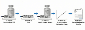
Calibration basics: exercise load cell + stable zero + apply known weight + multi-point methods for better performance across the operating range.
10.1 Calibration Basics
- Zero: establish a stable no-load baseline
- Span: calibrate with known reference loads across expected range
- Multi-point: improves accuracy across the working range
10.2 Accuracy Terms You’ll See on Datasheets
- Linearity: deviation from a straight-line response
- Hysteresis: difference between loading/unloading outputs
- Repeatability: variation across repeated measurements
- Creep: drift under constant load over time
- Temperature effects: changes in zero/span with temperature
- Zero balance/offset: no-load output (useful to detect overload damage)
10.3 Common Causes of Unstable Readings
- Off-center loading and platform flex
- Incorrect mounting introducing bending or side load
- Temperature swings without stabilization
- Moisture ingress in non-sealed designs
- Electrical noise (VFDs/motors), poor grounding/shielding
- Cable strain, corrosion, or intermittent shorts
10.4 Common Failure Modes (What Actually Breaks Load Cells)
- Overload beyond rated capacity (including shock loading)
- Side loads, torque, or misalignment
- Moisture ingress and corrosion
- Cable damage/abrasion and connector failures
- Long-term creep in high-temperature or continuous-load environments
If your system is drifting and you want a faster diagnosis path, isolate mechanical load-path issues first, then evaluate electrical noise/grounding and the conditioning electronics.
11) Load Cell Glossary (Engineer Terms)
These are common terms used in load cell datasheets and system design. Understanding them helps you compare sensors correctly and avoid installation pitfalls.
| Term | What It Means (Practical) |
|---|---|
| mV/V | Signal output per volt of excitation; a small analog bridge output that requires conditioning. |
| Excitation | Stable input voltage applied to the Wheatstone bridge (commonly 5–10V DC). |
| Linearity | How close the output follows a straight line across the range; impacts accuracy. |
| Hysteresis | Difference between loading vs unloading output at the same point. |
| Repeatability | How consistent readings are when the same load is applied repeatedly. |
| Creep | Output drift over time under constant load. |
| Zero Balance (Offset) | No-load output; changes can indicate overload or mechanical damage. |
| Span | Full-scale output range after calibration; tied to capacity and mV/V. |
| Resolution | Smallest detectable change; depends on sensor, electronics, filtering, and noise. |
| Side Load | Force not aligned with the intended axis; a common cause of drift and failure. |
| Overload / Shock Load | Loads beyond rated capacity or sudden impacts; can cause permanent deformation. |
| IP Rating | Ingress protection (dust/water resistance); important for washdown environments. |
| Hermetic Sealing | Sealed design to prevent moisture ingress; important for harsh environments. |
| Junction Box Trimming | Balancing multiple load cells so the platform reads consistently across corners. |
| EMI | Electrical noise from motors/VFDs; can destabilize low-level mV/V signals. |
| Sense Lines (6-wire) | Extra wires that compensate voltage drop in long cables for better accuracy. |
| Temperature Compensation | Design methods to reduce drift in zero/span across temperature changes. |
| Dead Load | Permanent load present (e.g., tank + structure); impacts capacity selection. |
| Live Load | Variable load measured during operation (product, material, payload). |
| Non-linearity from Mounting | Mechanical flex or side loads can create non-linear readings even with good sensors. |
| Filtering | Signal smoothing used to stabilize readings; too much can slow response. |
12) Standards & Accuracy Classifications
In regulated and high-precision environments, performance is described using recognized standards and accuracy classifications.
These frameworks help ensure the sensor meets repeatability and stability needs.
- OIML R60: international accuracy classes for load cells used in weighing instruments
- NTEP: U.S. legal-for-trade certification pathway for weighing systems
- ISO 376: calibration framework commonly referenced in force metrology contexts
Even with certified components, system performance depends on the entire measurement chain: sensor + mounting + electronics + calibration procedures.
FAQs
What is the difference between a load cell and a force sensor?
A load cell is a type of force sensor commonly optimized for weighing and stable force measurement using strain gauges. Other force sensors (such as piezoelectric)
may be more suitable for high-frequency dynamic measurements depending on bandwidth and application needs.
How accurate are load cells?
Accuracy depends on load cell design and the complete system installation. Key contributors include linearity, hysteresis, repeatability, creep, temperature effects,
mounting quality, and signal conditioning.
How long do load cells last?
With correct selection and installation, industrial load cells often operate accurately for many years. Longevity depends on overload exposure, sealing, cable protection,
and whether the load path prevents side loads and shock events.
Can I connect a load cell to a PLC?
Yes. Many systems use a transmitter/amplifier to convert mV/V to 4–20mA or 0–10V, or use a digital module (such as RS485/Modbus) depending on your control architecture.
Why do load cells drift over time?
Drift can be caused by temperature changes, mechanical creep, moisture ingress, electrical noise, or mechanical stresses outside the intended load path (side load/torque).
Diagnosis typically involves isolating mechanical vs. electrical factors.
Do you support OEM and custom load cell projects?
Yes. Transcell supports OEM integration including custom geometries, capacity ranges, sealing requirements, and output/interface needs, along with volume supply programs.
Why Engineers & OEMs Choose Transcell
- Industrial reliability: built for real environments where uptime matters
- Complete ecosystem: load cells plus indicators, amplifiers, transmitters, and junction boxes
- OEM programs: volume supply + engineering support for integration
- Metrology mindset: calibration support and system-level troubleshooting
- Fast response: direct access to technical support