BMF Micro S-Beam Load Cell
Tension & compression
Measures pulling and pushing forces in both directions · IP65 rated · alloy steel
Same-day shipping
In-stock orders ship the same business day · Free 2-day delivery
Manufacturer direct
Designed & supported by Transcell in Buffalo Grove, IL since 1981
2-year limited warranty
US-based technical support included · repair or replace guarantee
Product Description
BMF Series micro S-beam load cell overview
The BMF Series is an ultra-compact miniature S-beam load cell designed for tension and compression force measurement in applications where size is the primary constraint. At just 19.1 x 16.6 x 8.7 mm with a 3/4 in overall height, the BMF fits inside enclosures, robotic end-effectors, medical devices, and OEM instrument assemblies where no standard-size load cell could be accommodated. Despite its miniature form factor, the BMF uses a true S-beam geometry for accurate bidirectional measurement and provides a generous 250% safe overload rating, protecting against the handling and assembly mishaps common when working at small scales. All six variants share an identical body and mounting pattern, allowing capacity and material to be changed without modifying the surrounding fixture or wiring. Available in aluminum or stainless steel construction across imperial (5 lbf, 10 lbf, 25 lbf) and metric (20 N, 50 N, 100 N) ranges, with a 1.5 m braid-shielded silicone rubber cable and IP65 environmental protection.
|
Capacity range
5 lbf
to 25 lbf / 20 N to 100 N
|
Nonlinearity
±0.05%
of rated output
|
Construction
Alum. / SS
IP65 / 3/4 in height
|
Safe overload
250%
of rated capacity
|
Typical applications
The BMF is commonly specified wherever a true bidirectional force sensor must fit inside a constrained space — robotic systems, medical instruments, miniature test equipment, and OEM force-sensing modules where standard load cells are simply too large.
|
|
|||||
|
|
|||||
|
|


Technical notes
|
Installation and mounting
Load is applied through the threaded mounting holes only — never through the housing body. Imperial models use 4-40 UNC threads; metric models use M3 x 0.5. Do not exceed the listed thread engagement depth. Mount to a clean, flat, rigid surface and apply torque only to the mounting screws, never to the housing or cable. Route the cable with a strain relief to prevent mechanical loading at the cable entry point. All six BMF variants share the same 19.1 x 16.6 x 8.7 mm body and mounting pattern, allowing the capacity or material to be swapped without changing the fixture design. |
System integration
The BMF produces a 1.0 to 1.3 mV/V analog output signal (model dependent) and is compatible with any standard force indicator, DAQ system, or PLC analog input accepting a mV/V bridge signal. It ships with a 1.5 m braid-shielded 4-conductor 28 AWG silicone rubber cable, which provides flexibility and chemical resistance suited to medical and lab environments. OEM customization including cable length, connector type, and capacity is available on request. |
|
Cable wiring
The BMF ships with a 1.5 m (5 ft) braid-shielded 4-conductor 28 AWG silicone rubber integrated cable. Standard color code:
|
Ordering notes
Specify the model number for the required capacity and unit system. All six variants are dimensionally identical and interchangeable within the same fixture:
|
Specifications
| Model | BMF-5lbF | BMF-10lbF | BMF-25lbF | BMF-20N | BMF-50N | BMF-100N |
| Capacity | 5 lbf | 10 lbf | 25 lbf | 20 N | 50 N | 100 N |
| Material | Aluminum | Aluminum | Stainless Steel | Aluminum | Aluminum | Stainless Steel |
| Rated output | 1.2 mV/V | 1.0 mV/V | 1.2 mV/V | 1.1 mV/V | 1.1 mV/V | 1.3 mV/V |
| Mounting thread | 4-40 UNC (imperial models) | M3 x 0.5 (metric models) | ||||
| Body dimensions | 19.1 x 16.6 x 8.7 mm | |||||
| Nonlinearity | ±0.05% of rated output | |||||
| Hysteresis | ±0.05% of rated output | |||||
| Non-repeatability | ±0.05% of rated output | |||||
| Safe overload | 250% of rated capacity | |||||
| Input / Output impedance | 350 ± 10 Ω input · 350 ± 3 Ω output | |||||
| Insulation resistance | ≥5,000 MΩ at 50V DC | |||||
| Compensated temp. range | −10 to +40°C | |||||
| Safe temp. range | −20 to +60°C | |||||
| Environmental protection | IP65 | |||||
| Cable | 1.5 m · 4 × 28 AWG · braid-shielded silicone rubber | |||||
Dimensions / 3D Drawings
Note: You may need a software that can open/view STEP files.
-
Data Sheets
Interchangeable
Frequently Bought Together
-
Capacity: 10 N to 50 kN
 Free 2-Day Shipping
BAB-MT2 Ultra Performance S-Beam with Enhanced Safe Overload Protection (Metric)
Price range: $335.00 through $465.00 Select options This product has multiple variants. The options may be chosen on the product page -
Capacity: 50 to 200 lb
 Free 2-Day Shipping
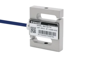
BSA Series S-Beam Load Cell
$185.00 Select options This product has multiple variants. The options may be chosen on the product page -
Capacity: 225 to 11K lbfFree 2-Day Shipping
BAB-MT2 Ultra Performance S-Beam with Enhanced Safe Overload Protection (Imperial)
Price range: $335.00 through $465.00 Select options This product has multiple variants. The options may be chosen on the product page
Ask us about our OEM and Dealer Pricing
Insights
Accurate and Reliable Force Feedback Using Load Pins
Industries
Experience to Solve Your Problems
Proven product quality and performance combine with our engineering experience to solve force measurement challenges in any industry that needs load cells and related force sensing equipment.