
Skip to content
Free 2-Day Shipping For All Orders Nationwide. No Minimum PurchaseFree 2-day shipping, no minimum
Home / Shop / Load Cells / S-Beam Load Cells

S-Beam Load Cells

Designed, built and calibrated in-house.
Free shipping across the USA.

Built and calibrated in-house.Talk to an engineer

Decide

Not sure which one? Two ways to narrow it.

Size it for me

Give us the load you actually need to weigh or pull. We will size the load cell against it and name the model, using the same rule our engineers use.

The heaviest load on the load cell in normal use, including anything hanging with it.

How far past its rating the load cell survives undamaged. Standard is 100% to 150%. Extra is anything above that, up to 10×.

Certified for buying and selling by weight.

The threaded holes it mounts through, and the rod ends, eye bolts and hardware that screw into them. Search any size. Our standard sizes narrow the answer below, and one we do not carry goes straight to an engineer as a custom build.

Pre-filled with a 1,000 lb example. Type over it. We add headroom (1.25× steady, 1.5× extra), then match the nearest rated capacity in a family that meets the rest of your answers. Genuine shock and impact wants more than either: send us the details and we will size it properly.

Every S-beam at a glance

The whole family on one screen: range, accuracy, direction and legal-for-trade status. Model names go to the product pages.

The S-beam engineering reference.

How the S-shape reads force in both directions, how to size a capacity you will not regret, and how to mount one so the number it gives you is true.

How they work

One web. Two directions.

An S-beam takes its name from the shape of the elastic element: a body machined so that a single web carries the load between two threaded connections. Load goes in at one thread and out at the other, so the load cell sits in the load path rather than underneath it.

The S-shape, and why it reads both ways

Force applied through the threaded connections is carried by a thin web across the middle of the body. Foil strain gauges bonded to that web change resistance as it deforms, and four of them wired as a Wheatstone bridge turn that into a millivolt signal proportional to load.

Because the geometry is symmetric about the mid-plane, pulling the connections apart strains the web one way and pushing them together strains it the other. The bridge outputs positive millivolts for one direction and negative for the other, which is why a single S-beam covers tension and compression without any change of hardware.

The curved arms either side of the web absorb moments that arrive off-axis, so an S-beam tolerates a degree of mounting misalignment that a bending beam would not. It is still an axial sensor, and alignment is still the thing that decides whether you get the accuracy on the data sheet.
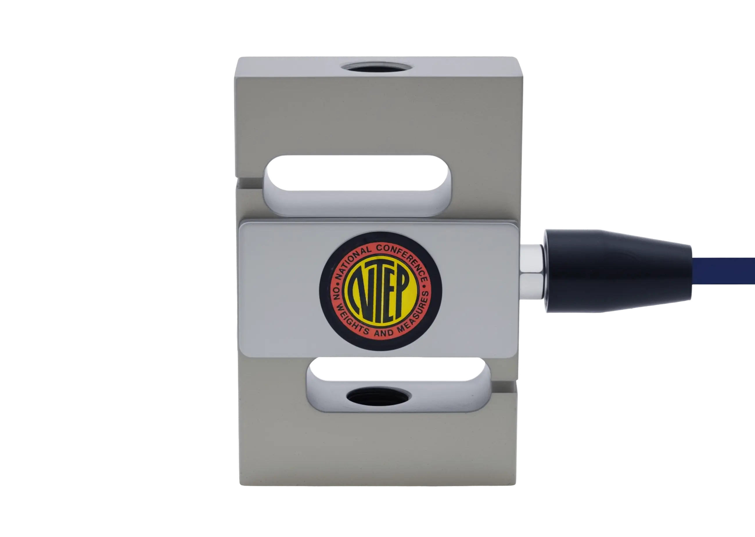
Transcell BSS S-beam load cell showing the machined S-shaped elastic element

Go deeper

Why the strain gauges sit on the web, not the curved arms

The web is the only part of an S-beam where strain is a clean function of axial load. It sits on the neutral axis of the body, which means bending moments arriving from off-axis load produce roughly equal and opposite strain above and below it, and those cancel in the bridge.

The curved arms do the opposite job. They are compliant by design, so a moment applied perpendicular to the load axis is absorbed as elastic deflection in the arms rather than being transmitted into the web. That is the mechanism behind an S-beam's tolerance of imperfect mounting, and it is why gauging the arms would destroy the very property that makes the geometry useful.

It also sets the limit. The arms can only absorb so much before the web starts seeing the moment as apparent load, which is why an S-beam is more forgiving than a bending beam but less forgiving than a shear beam at the same capacity. Past that point the error is indistinguishable from real force, because to the bridge it is real strain.

How a single element reads both directions

Four foil gauges are bonded to the web and wired as a Wheatstone bridge, arranged so that under load two of them stretch and two of them compress. Opposite arms of the bridge therefore move in opposite directions, and their contributions add rather than cancel.

Reverse the load and every gauge reverses with it. The bridge output changes sign, so the same load cell reads pull as positive and push as negative. On the BSS, rated output is 3.05 mV/V, which is 30.5 mV at the rated 10 V excitation. That is why one part number covers pull and push with no change of hardware.

The same arrangement is what makes the load cell insensitive to temperature. A uniform temperature change affects all four gauges equally, and because they sit in opposing arms the effect cancels at the output rather than showing up as drift.

What the S-shape gives up

Height. The load path runs through the long axis of the body, so an S-beam needs vertical room between its two connection points. Where clearance is the constraint, a pancake or a load button does the same job in a fraction of the height.

Capacity headroom. Our S-beams top out at 20,000 lb. Beyond that, a pancake or column load cell carries the load.

Lateral tolerance. An S-beam handles a few degrees of misalignment through its arms, but it is still an axial sensor. If side load cannot be designed out, a shear beam tolerates it better and will hold its accuracy where an S-beam will not.
Sizing

Capacity and accuracy. Size it once.

Size the load cell so that normal working load lands between 30% and 80% of rated capacity. Below that you give away resolution; above it you have no headroom for shock.

Sizing the capacity

Start with everything that hangs from the load cell permanently: the hook, the shackle, the fixture, the empty vessel. That dead load is on the element before anything is weighed, so it comes out of the working range first.

Then decide what kind of load it is. A steady pull or a slowly filled hopper takes the working load times about 1.25; a load that swings, jolts or is lifted off the floor takes about 1.5. Pick the next capacity up. The selector at the top of this page does that arithmetic.

Safe overload is a survival figure, not headroom. The BSS and BSA take 150% of rated capacity, the BMF 250%, and the BAB-MT2 between 3× and 10× depending on capacity, which is the reason to choose it where a specimen can break or a load can drop. Nothing read during an overload is a measurement.

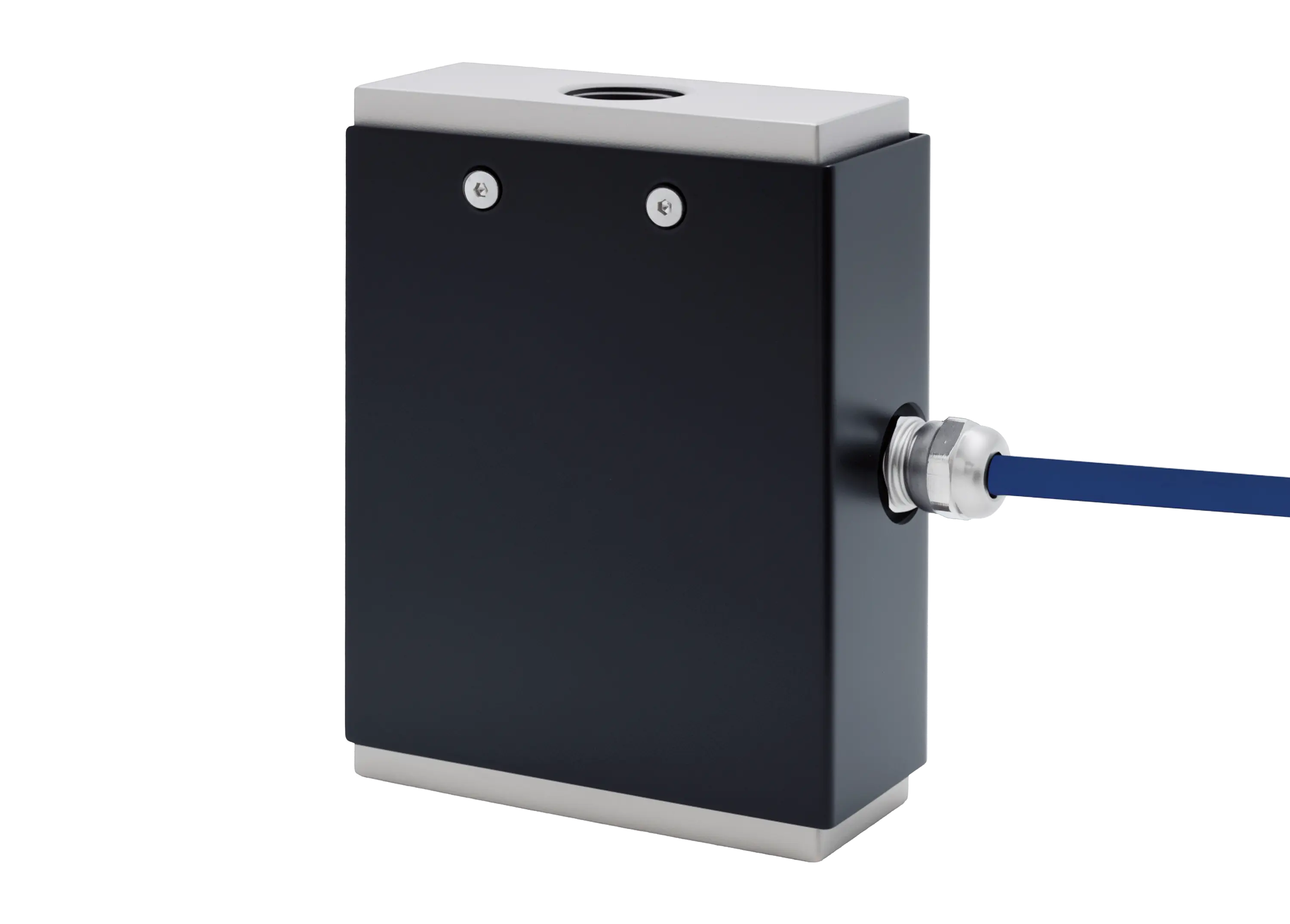
Transcell BAB-MT2 Ultra Performance S-beam load cell
Capacity bandFamilyNonlinearityTypical use
5 to 25 lbf / 20 to 100 NBMF micro±0.05%Bench force measurement, R&D rigs, small OEM assemblies
50 to 200 lbBSA±0.03%Light tension links, small hanging scales, product testing
2 to 11,000 lbfBAB-MT2±0.03%Precision testing and R&D where enhanced overload protection matters
250 to 20,000 lbBSS±0.02%Hoppers, tanks, crane and hanging scales, batching, process control

Exact capacities, tolerances and certification coverage are on each product page. NTEP Certificate of Conformance 97-028 covers BSS from 250 lb through 2,500 lb only.

Go deeper

Not every S-beam gives the same signal

Rated output differs by family. The BSS is 3.05 mV/V, so 30.5 mV at full load on the rated 10 V excitation. The BAB-MT2 is 2 mV/V, or 20 mV at 10 V. The BMF runs 1.0 to 1.3 mV/V depending on the model.

Two things follow. Check that the instrument's input range suits the signal, because a smaller signal uses less of it. And never mix sensitivities on one summing junction box: its trim resistors are there for the small differences between load cells of one family, not a gap that size.

Mounting

Accurate on one axis. Mount it that way.

Load that arrives at an angle puts bending into the web, and the bridge cannot tell that apart from real force. It also fatigues the element faster than rated cycling ever will.

The hardware that keeps load axial

The fix is mechanical. Rod-end bearings give a self-aligning connection that absorbs small angular error. Clevis pins allow rotation about the pin, which matters on crane and hanging installations where the load can swing. Spherical washers do the same job where a direct threaded stud is unavoidable.

Thread size follows capacity, so match the hardware to the model rather than to a general rule. On the BSS it is 3/8in-24 UNF at 250 lb, 1/2in-20 UNF from 500 to 3,000 lb, 3/4in-16 UNF at 5,000 and 10,000 lb, and 1-1/4in-12 UNF at 20,000 lb. The dimensions table on each product page gives the exact thread for every model.

Route the cable so it cannot carry load. Clamp it to the fixed side, never to the side that moves, and leave a loose loop at the load cell. The connection is four-wire with no sense lines, so the cable is part of the calibration: coil the excess rather than cutting it. The BSS and BSA ship with 20 ft (6 m), the BAB-MT2 with 9 ft, the BMF with 5 ft (1.5 m).

Read the installation guide

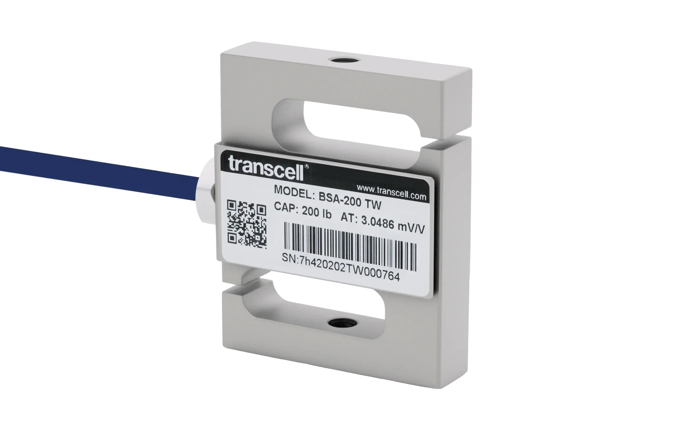
Transcell BSA S-beam load cell, with a threaded load hole at the top and bottom of the body

Hardware, in detail

Rod-end bearings

A rod end is a threaded shank carrying a spherical bearing. Screwed into the load cell's threaded connection, it lets the attached member swivel through several degrees while the force stays on the load cell's measuring axis. It is the default answer wherever the two mounting points cannot be guaranteed collinear, which in a fabricated frame is almost always.

Specify the bearing's static radial rating above the load cell's safe overload, not above its rated capacity. A load cell that survives a 150% excursion is of no use if the rod end fails first. Match the thread to the capacity band rather than to a general rule, because it changes across the range.

Clevis pins and brackets

A clevis is a U-shaped bracket with a pin through both ears and through the load cell's connection. Unlike a rod end, it allows rotation about one axis only, which is exactly what you want on a crane or hanging installation where the load swings in a predictable plane.

Pin shear strength has to exceed the load cell's safe overload rating with margin, and the pin should be a close fit in the bore. A loose pin lets the assembly shift under alternating load, which shows up as hysteresis in the reading long before it shows up as a mechanical problem.

Spherical washers and direct stud mounting

Where a threaded stud goes straight into the load cell with no bearing, a matched pair of spherical washers between the load cell and the frame takes up angular error. The convex and concave faces slide against each other during tightening and then lock, so the joint ends up square to the load path even when the surfaces it bolts to are not.

Direct stud mounting with no compensation is acceptable only when the load path is verified axial. Any angular error left in the joint becomes a permanent offset that no calibration will remove, because it varies with load.

Thread engagement and torque

Thread rods into the load cell by at least one full thread diameter. Less than that and the joint carries load on the first few threads only, which concentrates stress exactly where the section is smallest. On a 1/2 inch connection that means half an inch of engagement as a minimum.

Do not use the load cell body to react tightening torque. Hold the flats or the wrench feature on the fitting, never the load cell, and never apply torque through the element. A load cell that has had a rod tightened against its own body may read correctly at zero and still be out of specification under load, because the element has been pre-stressed.

Exact thread sizes for every capacity are in the dimensions table on each product page.

Applications

Where S-beams get used. And why.

Wherever force runs in a straight line between two points that can take a thread: a load hanging from a frame, a link being pulled, or a ram pushing in line. Reading both directions with one part is what keeps them there.

Questions

Before you specify one. The questions that come up.

What is an S-beam load cell?

A strain-gauge force sensor whose elastic element is machined into an S shape, with threaded connections at both ends. Load passes axially through the body and is carried by a web across the middle, where the strain gauges sit. The geometry reads tension and compression at the same sensitivity, which is why S-beams are the default for hanging and inline force measurement.

Can an S-beam measure both tension and compression?

Yes. The elastic element is symmetric, so pulling the connections apart and pushing them together strain the web in opposite directions. The bridge outputs positive millivolts for one and negative for the other. Rated capacity applies in both directions on our S-beam families.

What capacity should I choose?

Size so that normal working load falls between 30% and 80% of rated capacity. In practice that means multiplying your working load by about 1.25 for a steady application, or by 1.5 if it sees extra dynamic load, then picking the next capacity up. Genuine shock or impact needs more than either, so send us the details. The selector at the top of this page does that arithmetic and names the model.

Which S-beams are NTEP certified?

The BSS carries NTEP Certificate of Conformance 97-028 on capacities from 250 lb through 2,500 lb. Capacities above 2,500 lb fall outside that certificate, so they are not legal for trade. If the weight is the basis of a commercial transaction, stay inside the certified range or talk to us about alternatives.

Do I need rod ends or clevis hardware?

Strongly recommended on any installation where perfect axial alignment cannot be guaranteed. Rod-end bearings and clevis pins let the assembly find its own line under load, which keeps force on the measuring axis. Thread sizes are capacity specific, so match hardware against the dimensions table on the product page rather than a general figure.

What do I need besides the load cell?

An instrument that accepts a mV/V bridge input: an indicator, a transmitter, or a signal conditioner if a PLC is reading it. If more than one load cell shares a load, a summing junction box balances them before the signal reaches the instrument. Everything is in the same catalog and ships together.

Can you build a custom S-beam?

Yes, and routinely. Cable length, connectors and capacity within an existing body are standard modifications. Beyond that we adapt mounting geometry, integrate electronics, and design ground up for extreme environments and private label programmes.

We Make Your Challenge Our Business

Tell us what it has to do and we’ll tell you what it takes.

Contact Us