
Junction Boxes & Summing Cards
Load cell junction boxes and summing cards, designed, built and tested in-house.
Free shipping across the USA.
Not sure which one?
Junction boxes and summing cards
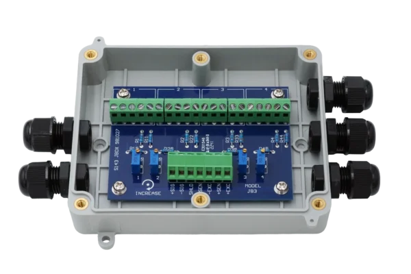
JB-FI-4
The default four-channel box.

JB-FI-4
Excitation trim, same price.

JB-FI-6
Six channels, chains to 12.

JB3V
IP68 and vented, for pits.

JB-SS-4
Stainless, for washdown.

JB-SS-6
Six channels in stainless.

JB-SS-8
Eight channels, one box.

AJB-015
Temperature-compensated.

JB-PCB-4
The JB-FI-4 board, on its own.

JB-PCB-4 Narrow
124 × 26 mm board.

JB-PCB-4
Excitation trim, board only.

JB-PCB-6
Matches the 6-channel boxes.

JB-PCB-8
Most channels on one card.

Splicing Box
Joins or extends one cable.
Custom & OEMWe also build the ones that aren’t in any catalog. Learn more
No catalog match for that combination.
That usually means it's a custom build, and custom summing boards and enclosures are a core part of our business. Tell us the channel count, the trim method and where it has to survive, and our engineers will take it from there.
Everything else the system needs. One catalog, one order.
A junction box never works on its own. Load cells, instruments and cable all come from the same catalog, on the same order.
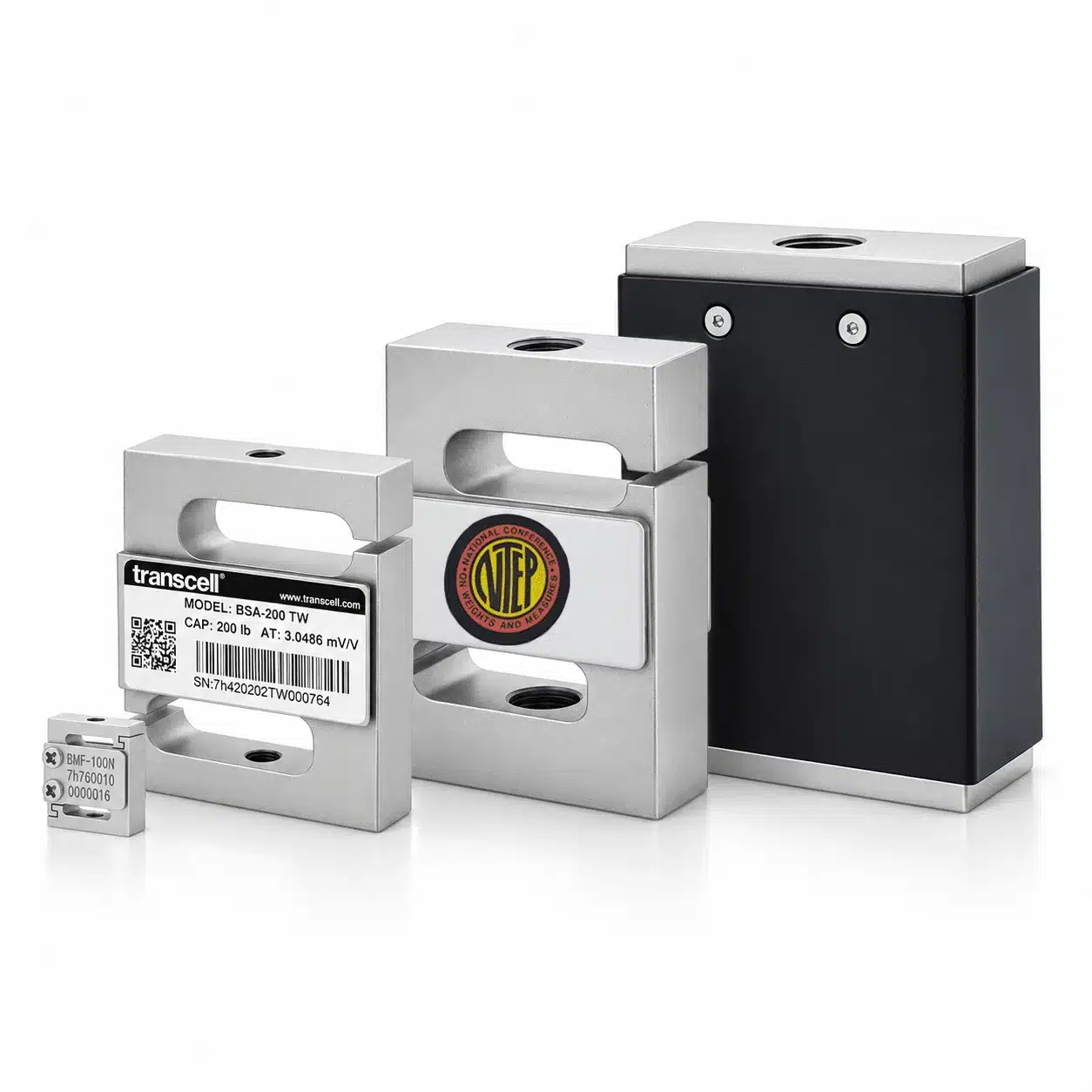
Load Cells
What is being summed. Twelve families, designed, built and calibrated in the same building, so the load cells sharing a box actually match.
View products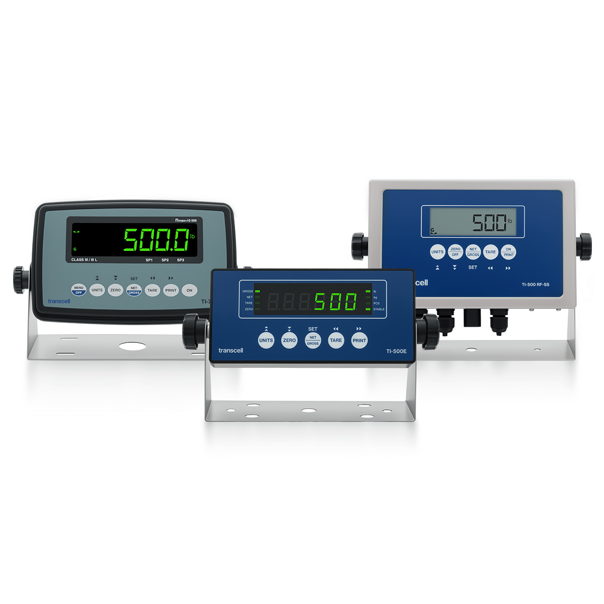
Digital Indicators
What the homerun cable lands on. Its excitation supply, not the box, sets how many load cells the whole system can carry.
View products
Cables & Accessories
Shielded 4-conductor cable by the reel, glands and quick disconnects. Cable is where most noise complaints actually start.
View productsWhy Transcell. Ordered like a store, backed like a partner.
Free 2-day shipping
Free 2-day shipping on every USA order, Alaska and Hawaii included, no minimum.
Ships worldwide
International orders ship at FedEx live rates: what FedEx charges is what you pay.
Warranty backed
Every product carries a manufacturer warranty. If something goes wrong, you deal with the people who built it.
Custom when you need it
Can't find the perfect fit? We build custom load cells and custom electronics for OEMs every day.
Junction box reference
How to choose a load cell junction box: whether you need the enclosure or only the card inside it, how many load cells it has to sum, whether the trimmers should act on the signal or on the excitation, where it has to survive and what the homerun cable lands on. Below, each of those in turn, what a summing card actually does to the signal, every model side by side, the corner balancing procedure, the wiring, and the terminology.
Which junction box do you need? What decides the part number.
Every product here does the same two things: it parallels excitation out to several load cells and sums their outputs back into one signal, with a trimmer on each channel. What separates them is the channel count, whether the trimmers sit in the signal path or the excitation path, and what the enclosure has to survive. Work through these in order and the part number usually picks itself.
Do you need the box, or just the card?
This is the first fork because it changes the price more than anything else on the page. A complete junction box is the summing card already mounted in a sealed housing, with a cable gland for every load cell plus one for the homerun cable, screw terminals landed and a grounding post for the shields. It is what you order for a new installation, and it is what you want if anyone other than you is going to open it later.
A summing card on its own is the same electronics without the housing. It is the right part in exactly two situations. The first is a repair: a board has been damaged, usually by water that got past a gland or by a lightning event on a long cable run, and the enclosure itself is fine. The JB-PCB-4, JB-PCB-6 and JB-PCB-8 drop straight back in. The second is OEM work, where the summing network is being built into a machine frame or a customer's own enclosure rather than into a standalone box.
The size of the board matters when you are fitting it into something that was not designed around it. The standard JB-PCB-4 is 100 × 75 mm, roughly square. The narrow version carries the same four channels on a 124 × 26 × 17 mm strip, which is the part to specify when the available space is a slot rather than a square.
One product on this page belongs to neither group. The Load Cell Splicing Box has no summing card and no trimmers at all: it exists to join or extend a single load cell cable inside a sealed housing, which is the correct alternative to a wire nut and a wrap of tape.
How many load cells does it have to sum?
Count the load cells, then buy that channel count or the next one up. Four channels covers the JB-FI-4, JB3V, JB-SS-4 and AJB-015, which is by far the most common requirement. Six is the JB-FI-6 and JB-SS-6. Eight in a single enclosure is the JB-SS-8. Unused channels are not a problem: the JB-FI boards are specified to sum from two load cells upward, so a four-channel box running three load cells is a normal configuration, not a compromise.
The JB-FI boards also daisy-chain. Two JB-FI-4 cards and enclosures sum eight load cells, and two JB-FI-6 cards and enclosures sum twelve. That is worth knowing when a structure grows after the fact, because it means an existing installation can be extended rather than replaced. It is not free of consequence though: two boxes mean two sets of glands, two sets of terminations and a longer interconnect, all of which are places for water and noise to get in. Where a single enclosure will do the job, use one.
The number that actually caps a system is usually not printed on the junction box at all. Load cells wire in parallel, so each one added divides the total bridge resistance and draws more current from the instrument's excitation supply. That supply is the limit. Most of our digital indicators drive four or eight 350-ohm load cells, and the TI-1680 drives twelve. Summing eight load cells into an instrument rated for four does not work, no matter how good the box is.
The other constraint is that the load cells being summed have to be the same capacity and the same nominal output. Trimming corrects small differences in rated output between load cells of the same type. It cannot reconcile a 1,000 lb load cell with a 2,500 lb one, because they are producing fundamentally different millivolts for the same load.
Signal trim or excitation trim?
Both methods solve the same problem, which is that two load cells of the same nominal rating do not produce precisely the same output for the same load. The difference is where in the circuit the correction is applied.
Signal trim puts the multi-turn potentiometer in the signal path, attenuating the millivolts returning from the load cell that reads high until it agrees with the others. It is the default on this page and the method almost every field balancing procedure is written around, including the one below. It works with any instrument, and there is nothing about it the instrument needs to know. The JB-FI-4 Signal Trim, JB-FI-6, JB3V, all three JB-SS boxes, the AJB-015 and four of the five summing cards use it.
Excitation trim reduces the excitation voltage delivered to that load cell instead. Because a load cell's output is a ratio of its excitation, dropping the excitation to a high corner scales its output down proportionally, and the correction happens before the measurement rather than after it. Nothing is inserted into the signal path. It is available here on the JB-FI-4 Excitation Trim box and the JB-PCB-4 Excitation Trim card.
In practice the decision is usually made for you. Order excitation trim when your instrument's manual, your scale manufacturer or your customer's specification calls for it, and order signal trim otherwise. On the JB-FI-4 the two versions are the same enclosure at the same $60, so the only thing you are choosing is the card inside, and the two are not interchangeable once the system is calibrated. As a rule, signal trim suits most general-purpose scales, while excitation trim holds linearity better and is the usual choice for high-accuracy systems. Sense wiring is the same on both versions: a 7-position output strip with the sense terminals jumped inside the box.
Where is the box mounted?
A junction box is almost always the lowest and least accessible part of the installation, usually bolted under a structure where water collects and where nobody looks until something reads wrong. The housing is therefore worth more attention than the electronics, which are identical across the range.
ABS is the indoor answer. The JB-FI-4 is rated IP65, with glands accepting cable from 4.5 to 8 mm outside diameter and terminals taking 12 to 24 AWG. That covers dust and hose-directed water, which is enough for a bench, a warehouse floor or a dry production line.
IP68 is a different promise: continuous immersion rather than splashing. The JB3V is the model for it, in an ABS housing with stainless self-retaining cover screws and a breather vent. Both details matter more than they sound. Self-retaining screws stay in the lid, so nothing gets dropped into a pit during a service call. The vent lets water vapour out while keeping contaminants and liquid water from getting in, which is what stops condensation forming inside a sealed box that heats up during the day and cools at night. A perfectly sealed unvented enclosure outdoors will eventually rain on its own terminals.
Stainless steel is what food, chemical, pharmaceutical and outdoor coastal installations end up needing. It survives caustic cleaning chemicals and the corrosion that eventually chalks and cracks a plastic housing, and it takes the mechanical abuse of an area where things get hosed and knocked. The JB-SS-4, JB-SS-6, JB-SS-8 and AJB-015 are the stainless options. The AJB-015 is specified for −10 °C to 40 °C at under 95% humidity, non-condensing, which is the range to check against an unheated dock or a cold store before ordering.
What happens at the instrument end?
Everything the junction box does arrives at the instrument on one cable, and two details about that cable decide whether the installation is stable or intermittently strange.
The first is sense lines. The JB-FI output is a 7-position terminal strip with the sense terminals internally jumped, which means a 6-wire homerun cable can be landed at the box and the instrument's sense lines will read the excitation as it exists at the junction box rather than at the instrument. That is the point of 6-wire: it lets the instrument correct for voltage dropped in the homerun cable, which is otherwise a slow error that changes with temperature and cable length. On a short run in a stable room, 4-wire is fine. On a long run, outdoors, or anywhere the temperature swings, use the sense pair.
The second is the shield. Every load cell cable coming into the box has a shield, and the box provides a grounding post to land them on. The rule that matters is that the shield is grounded at one end only, normally at the instrument. Grounding both ends creates a loop between two points that are not actually at the same potential, and the current that flows around it lands as noise on a signal measured in millivolts. Transcell's load cell wiring guide covers the full colour code and the step-by-step procedure.
Finally, the cable itself. Load cell signal is small enough that cable choice is a real specification, not an afterthought: use shielded load cell cable, keep it physically away from motor leads and variable-frequency drives, and do not run it in the same conduit as anything switching power. The most common noise complaint on a summed platform is not the junction box at all.
What a summing card actually does. Several signals in, one out.
A junction box is passive. It has no power supply of its own, nothing is amplified and nothing is converted. It parallels one excitation supply across several load cells, adds their outputs together through a resistor network, and gives you a way to weight each one before it is added.
01
Excitation in, split out
One 5–10 V DC supply arrives from the instrument and is paralleled to every load cell. This is why the instrument, not the box, caps the load cell count.
02
Signals return
Each load cell sends back a few millivolts proportional to its own share of the load. Nominally identical load cells return slightly different values.
03
Each channel trimmed
A sealed multi-turn trimmer per channel scales that load cell up or down. Multi-turn is what makes a fine adjustment repeatable by hand.
04
Summed to one signal
The trimmed outputs are combined through temperature-compensated resistors into a single mV/V signal, an average of everything on the structure.
05
Out on the homerun
Excitation, sense, signal and shield land on one 7-position strip and leave on one cable to the instrument.
Because the summing network is passive and resistive, its accuracy over time is a materials question rather than an electronics one. The AJB-015 is built on high-accuracy temperature-compensated resistors and sealed low-drift multi-turn trimmers for exactly that reason: a trimmer that drifts with temperature turns a balanced structure into an unbalanced one every afternoon.
The fast mapping. Where most installations land.
Each row links straight to that product.
| If you are building | Start here | Why |
|---|---|---|
| Four load cells, indoors and dry | JB-FI-4 Signal Trim | The default configuration and the lowest cost of entry. IP65 ABS, four multi-turn trimmers, glands for 4.5 to 8 mm cable and a 7-position output with sense jumped. |
| Four load cells, washdown or food area | JB-SS-4 or AJB-015 | Stainless survives caustic cleaning and the corrosion that eventually cracks a plastic housing. Same four channels, same signal trim. The AJB-015 adds temperature-compensated resistors and sealed low-drift trimmers, so it holds its corner balance better over time; the JB-SS-4 is the lower-cost choice. |
| Four load cells, outdoors or in a pit | JB3V | The only IP68 model here, with a breather vent that stops condensation forming inside and self-retaining cover screws that cannot be dropped during a service call. |
| Six load cells | JB-FI-6 or JB-SS-6 | Six channels in one enclosure, ABS or stainless. The JB-FI-6 also daisy-chains to twelve load cells with a second card and enclosure. |
| Eight load cells | JB-SS-8 or two JB-FI-4 | One stainless enclosure is the cleaner installation: a single set of glands, a single set of terminations and one place to open. Daisy-chaining is the answer when an existing four-channel box has to grow. |
| More than eight load cells | Two JB-FI-6 or talk to an engineer | Two JB-FI-6 cards and enclosures sum twelve. Check the instrument first: twelve 350-ohm load cells in parallel is more excitation current than most instruments supply. |
| An instrument or specification calling for excitation trim | JB-FI-4 Excitation Trim | Same enclosure, same price, different card. The correction is applied to the excitation going out rather than the signal coming back, so nothing is inserted into the signal path. |
| A failed board in an enclosure that is otherwise fine | JB-PCB-4, JB-PCB-6 or JB-PCB-8 | Match the channel count and the trim type of the board you are replacing. Half the price of the complete box, and the glands, housing and mounting stay where they are. |
| A summing network inside a narrow or shallow housing | JB-PCB-4 Narrow | Four channels on a 124 × 26 × 17 mm strip instead of the square 100 × 75 mm board, for slots the standard card will not fit. |
| A damaged or too-short load cell cable | Load Cell Splicing Box | No summing and no trimming, just a sealed, properly terminated join. The correct alternative to splicing a shielded signal cable with wire nuts. |
| An OEM assembly in your own housing | Custom & OEM | Start from the bare summing cards, or have the board, enclosure, gland pattern and cable configuration built to your drawing and part number. |
Every product, side by side. Sorted by what differs.
Channel count, trim method and housing separate these faster than anything else on the datasheet.
| Product | Form | Load cells | Trim | Housing | Rating | Price |
|---|---|---|---|---|---|---|
| JB-FI-4 Signal Trim | Junction box | 2–4 · 8 chained | Signal | ABS | IP65 | $60 |
| JB-FI-4 Excitation Trim | Junction box | 2–4 · 8 chained | Excitation | ABS | Not published | $60 |
| JB-FI-6 Signal Trim | Junction box | 2–6 · 12 chained | Signal | ABS | IP65 | $80 |
| JB3V | Junction box | 4 | Signal | ABS, vented | IP68 | $85 |
| JB-SS-4 | Junction box | 4 | Signal | Stainless steel | IP65 | $190 |
| JB-SS-6 | Junction box | 6 | Signal | Stainless steel | IP65 | $225 |
| JB-SS-8 | Junction box | 8 | Signal | Stainless steel | IP65 | $285 |
| AJB-015 | Junction box | Up to 4 | Signal | Stainless steel | IP65 | $230 |
| JB-PCB-4 Signal Trim | Summing card | 4 | Signal | Board, 100 × 75 mm | — | $30 |
| JB-PCB-4 Signal Trim Narrow | Summing card | 4 | Signal | Board, 124 × 26 × 17 mm | — | $30 |
| JB-PCB-4 Excitation Trim | Summing card | 4 | Excitation | Board | — | $30 |
| JB-PCB-6 Signal Trim | Summing card | 6 | Signal | Board | — | $85 |
| JB-PCB-8 Signal Trim | Summing card | 8 | Signal | Board | — | $100 |
| Load Cell Splicing Box | Splice box | Splices one cable | None | Sealed enclosure | — | $45 |
"Not published" means Transcell has not published that figure for the model, never that the enclosure is unsealed. A dash means the specification does not apply: a bare summing card has no enclosure rating. Load cell counts assume 350-ohm load cells of matching capacity wired in parallel; the instrument's excitation supply, not the box, sets the total the system can carry.
Balancing the corners. The procedure, in order.
Fitting the box is half the job. Until the channels are trimmed, the same load reads differently depending on which load cell is carrying most of it, and no amount of calibration at the instrument will fix that. This is Transcell's own procedure, and it takes about twenty minutes.
01
Open up the resolution
Put the instrument into 10× mode or internal count mode, so you can see far more resolution than the display normally shows.
02
Load the first position
Place a test weight of no more than 25% of rated capacity directly over the first load cell. Record the reading.
03
Repeat every position
Move the same weight over each remaining load cell in turn, recording each reading before moving on.
04
Trim to agreement
Adjust each trimmer until every position reads within ±0.5 d of the others. Clockwise raises a reading, counter-clockwise lowers it.
05
Close up and calibrate
Refit the lid and tighten the fasteners evenly, then run a full zero and span calibration from the instrument.
Three things go wrong here more than anything else. Overturning a multi-turn trimmer damages it, so approach the target rather than sweeping past it. Tightening the lid unevenly distorts the gasket and quietly costs you the enclosure rating, which is the most common cause of a box that leaks a year later. And balancing is not calibration: the corners agreeing with each other says nothing about whether the number is right, so the full calibration at the end is not optional. If a corner will not come into agreement at all, the problem is upstream, usually a load cell that is damaged, mismounted or of the wrong capacity, and Transcell's installation guide covers mounting and alignment.
Wiring, sealing and grounding. Where installations actually fail.
Nothing inside a junction box breaks on its own. What fails is a gland that was not tightened, a shield landed at both ends, or a lid closed unevenly. Four things to get right.
Terminals
Colour code and marking
Every terminal is marked. Excitation +EXC red, −EXC black; sense +SEN blue, −SEN brown; signal +SIG green, −SIG white; shield SHLD yellow.
The JB-FI takes 12 to 24 AWG on screw terminals, one 5-position strip per load cell.
Sense
The 7-position output
The output strip carries excitation, sense, signal and shield, with the sense terminals internally jumped. Land a 6-wire homerun there and the instrument senses excitation at the box.
Use the sense pair on long runs and outdoors. Skip it on a short run in a stable room.
Shield
Grounded at one end
Land every load cell shield on the box's grounding post. Ground the run to the instrument at one end only, normally the instrument.
Grounding both ends creates a loop, and the current around it lands as noise on a millivolt signal.
Sealing
Glands and the lid
Glands seal a range, not any cable: the JB-FI accepts 4.5–8 mm O.D., the JB3V's PG7 glands 4.0–5.6 mm. Undersized cable in an oversized gland does not seal.
Tighten lid fasteners evenly. Uneven torque distorts the gasket and the rating goes with it.
The full colour code, the 4-wire and 6-wire decision and the step-by-step installation sequence are covered in Transcell's load cell wiring guide, and mounting, torque and alignment in the load cell installation guide. One additional habit worth adopting on any structure that will be serviced later: leave a service loop of cable at each load cell, so a load cell can be replaced without re-pulling a run.
Datasheet terms, in plain language. What they mean when you're comparing.
Show all 24 terms
- Summing
- Combining the outputs of several load cells into one signal, so the instrument reads the total rather than any one of them.
- Summing card
- The passive board that does the summing and carries the trimmers. Sold inside an enclosure or on its own.
- Junction box
- A summing card in a sealed housing, with cable glands, terminals and a grounding post already fitted.
- Channel
- One load cell input on the card. A four-channel card takes four load cells and has four trimmers.
- Corner balancing
- Adjusting each channel so the same load reads the same wherever it sits on the structure. Also called corner adjustment.
- Trim pot
- The potentiometer used to make that adjustment. Multi-turn types take many rotations end to end, which is what makes a fine setting repeatable by hand.
- Signal trim
- Trimming that attenuates the millivolts returning from a load cell. The default method here and the one most field procedures assume.
- Excitation trim
- Trimming that reduces the excitation voltage sent to a load cell instead, so its output scales down before it is measured.
- Excitation
- The stable voltage the instrument supplies to the load cell bridges, commonly 5 to 10 V DC, paralleled across every load cell by the box.
- Signal
- The millivolt output a load cell returns, proportional to both the load on it and the excitation it is given.
- Sense lines
- An extra pair that lets the instrument measure the excitation as it actually arrives, correcting for voltage dropped in a long cable.
- 4-wire vs 6-wire
- 4-wire is excitation and signal only. 6-wire adds the sense pair, and matters on long runs and where temperature swings.
- Homerun cable
- The single cable leaving the junction box for the instrument, carrying the summed signal.
- Daisy-chaining
- Feeding one summing card's output into another to double the channel count, as on the JB-FI boards.
- Bridge resistance
- The resistance a load cell presents to the excitation supply, commonly 350 ohms. Load cells in parallel divide it.
- Excitation budget
- How many load cells the instrument's supply can drive. It is a current limit, not a count of inputs, and it caps the whole system.
- mV/V
- A load cell's rated output per volt of excitation. Load cells summed together should share the same rating.
- Division (d)
- The smallest increment the instrument's display steps in. Corner readings are balanced to within about half of one.
- Terminal strip
- The block of screw terminals a cable lands on. Five positions per load cell input, seven on the output.
- Cable gland
- The compression fitting that seals a cable where it enters the housing. Each one seals a stated diameter range, not any cable.
- Breather vent
- A membrane that lets water vapour out while keeping liquid and contaminants from getting in, so condensation does not build up inside.
- IP65 / IP68
- IP65 withstands dust and hose-directed water. IP68 withstands continuous immersion, which is what a pit installation needs.
- NEMA 4X
- The North American equivalent for a washdown, corrosion-resistant enclosure, usually stainless.
- Splice box
- A sealed enclosure for joining or extending a load cell cable, with no summing card and no trimmers in it.
Junction boxes, answered.
What does a load cell junction box actually do?
Two jobs. It parallels the excitation out to every load cell and sums their signal outputs onto one homerun cable, so the instrument sees a single averaged signal instead of several. And it gives every load cell its own multi-turn trimmer, so a load placed over one load cell can be made to read the same as the same load placed over any other. Without that second job the reading changes depending on where the load sits, and no amount of calibration at the instrument will correct it.
Do I need a junction box for a single load cell?
No. One load cell wires straight to the instrument, and there is nothing to sum and nothing to balance. A junction box earns its place the moment two or more load cells share the same structure. If all you need is to join or lengthen a load cell cable, the Load Cell Splicing Box does that on its own for $45, without a summing card in it.
Signal trim or excitation trim: which one do I order?
Signal trim is the default and it is what eleven of the fourteen products here use. The trimmer attenuates the millivolts coming back from one load cell, it works with any instrument, and it is the method almost every field balancing procedure is written around. Excitation trim adjusts the voltage going out to that load cell instead, so the correction happens before the measurement and nothing is added to the signal path. Order excitation trim when your instrument's manual or your customer's specification calls for it. On the JB-FI-4 both versions are the same enclosure at the same price, so the only thing you are choosing is the card inside.
How many load cells can one junction box sum?
Four on the JB-FI-4, JB3V, JB-SS-4 and AJB-015; six on the JB-FI-6 and JB-SS-6; eight on the JB-SS-8. The JB-FI boards also daisy-chain, so two JB-FI-4 enclosures sum eight load cells and two JB-FI-6 enclosures sum twelve. The real ceiling is usually the instrument rather than the box: load cells wire in parallel, so the indicator's excitation supply sets how many 350-ohm load cells the system can carry. Most drive four or eight; the TI-1680 drives twelve.
Can I buy the summing card without the enclosure?
Yes. Every JB-PCB part is the bare board on its own, in four, six and eight channel versions and in both trim types, at $30 to $100. That is the part to order when a board has failed inside an enclosure that is otherwise fine, and it is the part OEMs order when the summing network is being built into their own housing. The standard four-channel board is 100 by 75 mm; the narrow version puts the same four channels on a 124 by 26 mm strip for housings that will not take the square one.
How do I balance the corners after installation?
Put the instrument into 10× or internal count mode so you can see more resolution than the display normally shows. Place a test weight no greater than 25% of the rated capacity directly over the first load cell and record the reading, then repeat over each of the others. Adjust each trimmer until every position reads within about half a division of the others, turning clockwise to raise a reading and counter-clockwise to lower it, without overturning the trimmer. Reseal the enclosure with the fasteners tightened evenly, then run a full calibration from the instrument. The full sequence is above.
Will these work with load cells from another brand?
Yes. A summing card is passive and brand-agnostic, so any standard strain-gauge load cell with a mV/V bridge output wires in. What does matter is that the load cells being summed share the same capacity and the same nominal output, because trimming corrects small differences between comparable load cells and cannot reconcile load cells that are scaled differently. Our own load cells are built and calibrated in the same building as these boxes, which is the simplest way to keep one supplier accountable for the whole system.
What's the lead time, and is it in stock?
Every product on this page is a stock item and ships with free 2-day delivery nationwide. Custom boards, custom gland patterns and private-label assemblies are quoted with a lead time up front, so you know the date before you commit. In-stock orders usually ship the same business day.
Is there a minimum order?
No. There's no minimum purchase, and free 2-day shipping applies to every order regardless of size, whether that's one $30 replacement summing card or a full system's worth.
Do you offer OEM and volume pricing?
Yes. Summing boards are one of the easier things to build to a customer's own drawing: channel count, trim method, board outline, gland pattern, cable lengths and part numbering are all things we change routinely. Tell us the annual quantity and the configuration and an engineer will follow up. Dealer pricing is also available on request. The JB-FI, JB-SS and AJB-015 boxes, the JB-PCB summing cards and the splicing box carry a 2-year limited warranty; the JB3V carries 1 year.
We Make Your Challenge Our Business
Tell us what it has to do and we’ll tell you what it takes.