How they work
They read shear. Not bending.
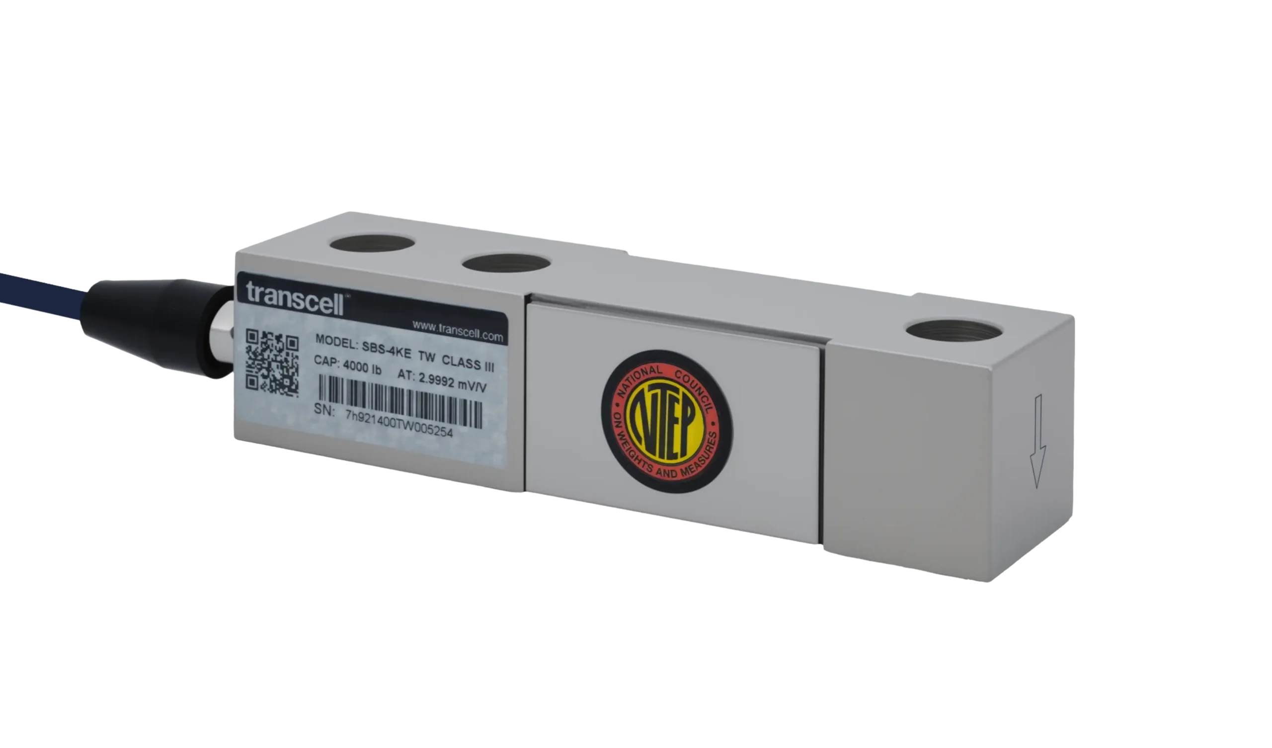
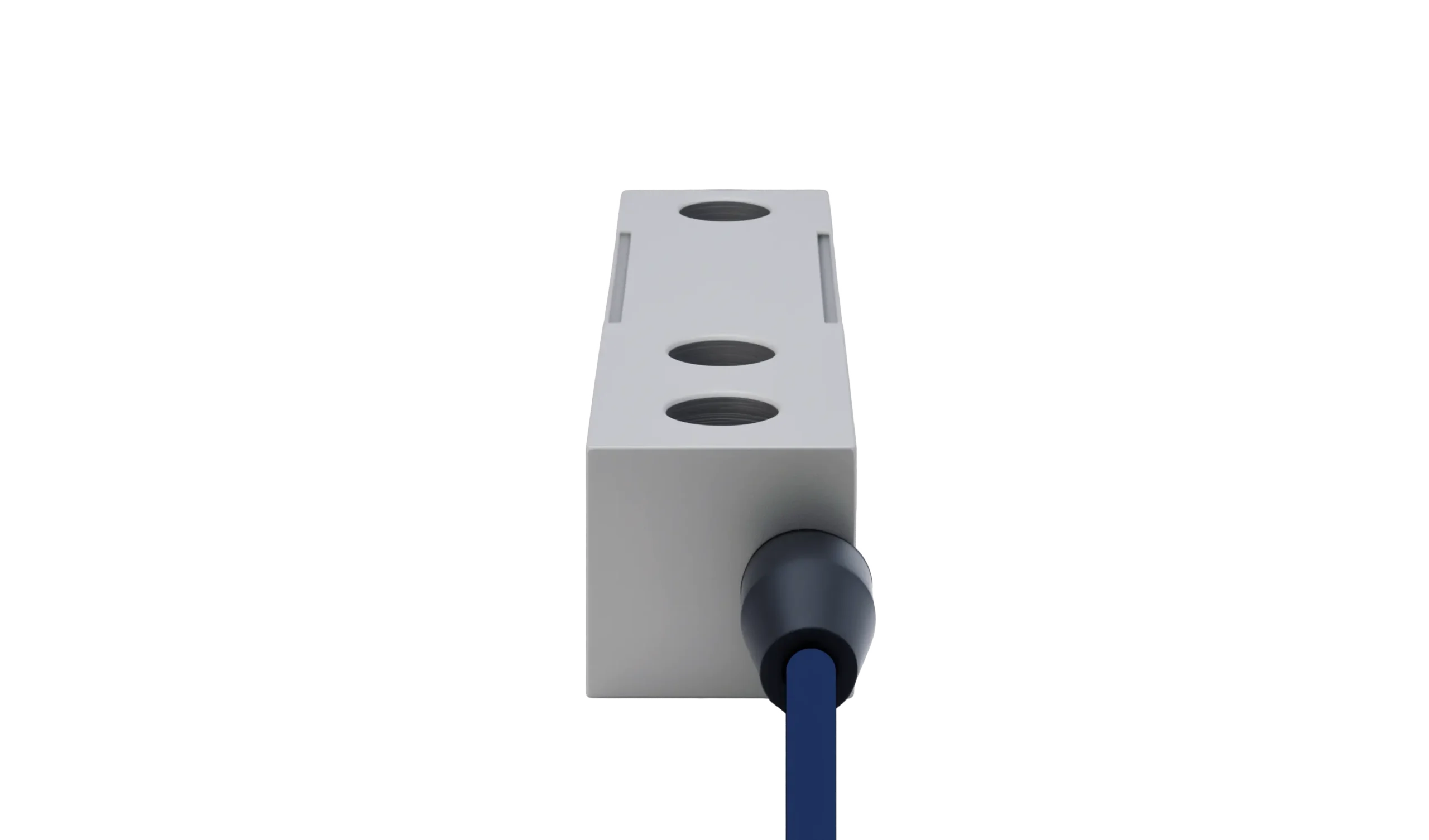
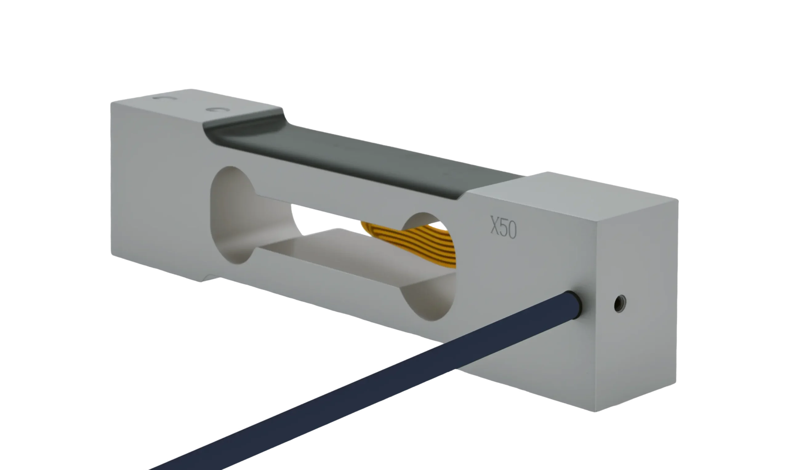
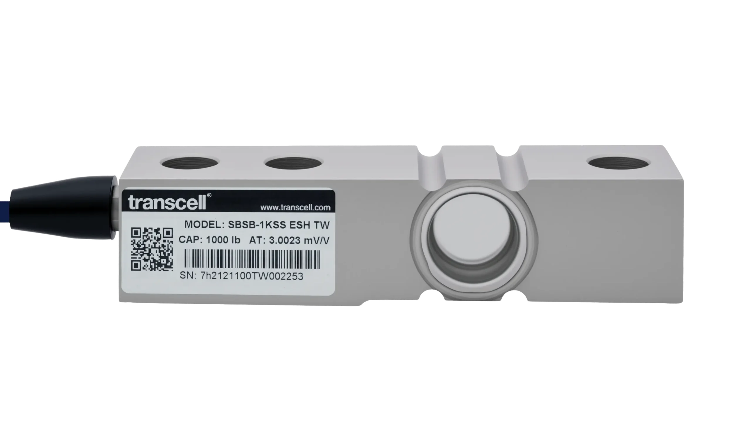
A single-ended beam is bolted down at one end and loaded at the other, which sounds like a bending beam and is not one. The gauges sit inside a machined cavity and read shear strain, and that one choice is what makes the geometry tolerant of where the load actually lands.
The blind cavity and the 45° gauges
Machined into the side of the beam is a pocket that does not go all the way through. What it leaves is a thin vertical web at the neutral axis, the one line through the beam where bending puts no strain at all, because the material above it is in tension, the material below is in compression, and the transition passes through zero.
The gauges are bonded to that web at 45° to the beam axis, because shear in a web appears as tension along one diagonal and compression along the other. Four of them in a bridge give an output proportional to the shear force crossing the section, and to nothing else.
The cavity is then closed: to IP67 on the alloy steel SBS, with a welded hermetic seal on the stainless SBSB. That closure is most of what separates the two families, because it decides how long the specification survives the environment rather than what the load cell reads.
Go deeper
Why the load position along the beam stops mattering
Take the beam as a cantilever and cut it anywhere between the bolted end and the point where the load arrives. Two internal actions cross that cut. The shear force equals the applied load, full stop. The bending moment equals the applied load multiplied by the distance from the cut to the load. Distance is in one expression and not the other: gauges reading bending see a signal that changes as the load moves along the beam, gauges reading shear see the same number wherever it sits.
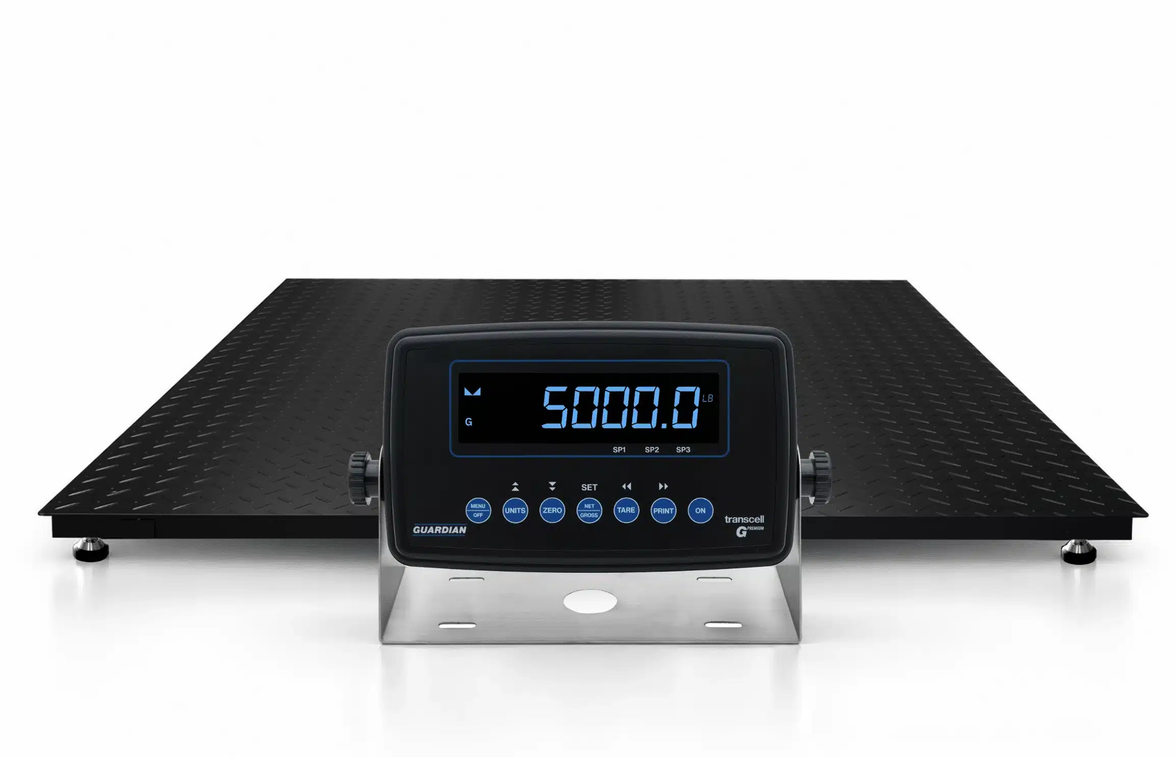
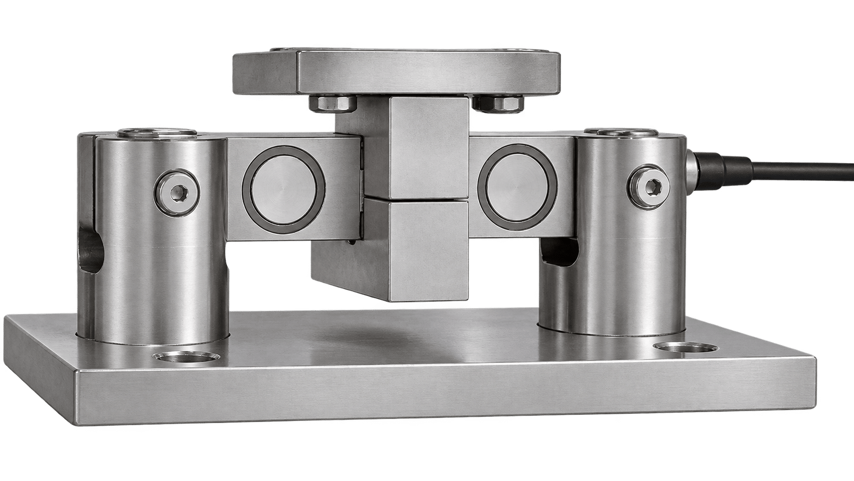
That buys tolerance, not indifference: the loading hole is still where the load is meant to arrive. But a load that lands off its centreline, or through a foot that has rocked out of position, reads correctly anyway, which is why shear beams end up under decks and vessels where the load path is built on site.
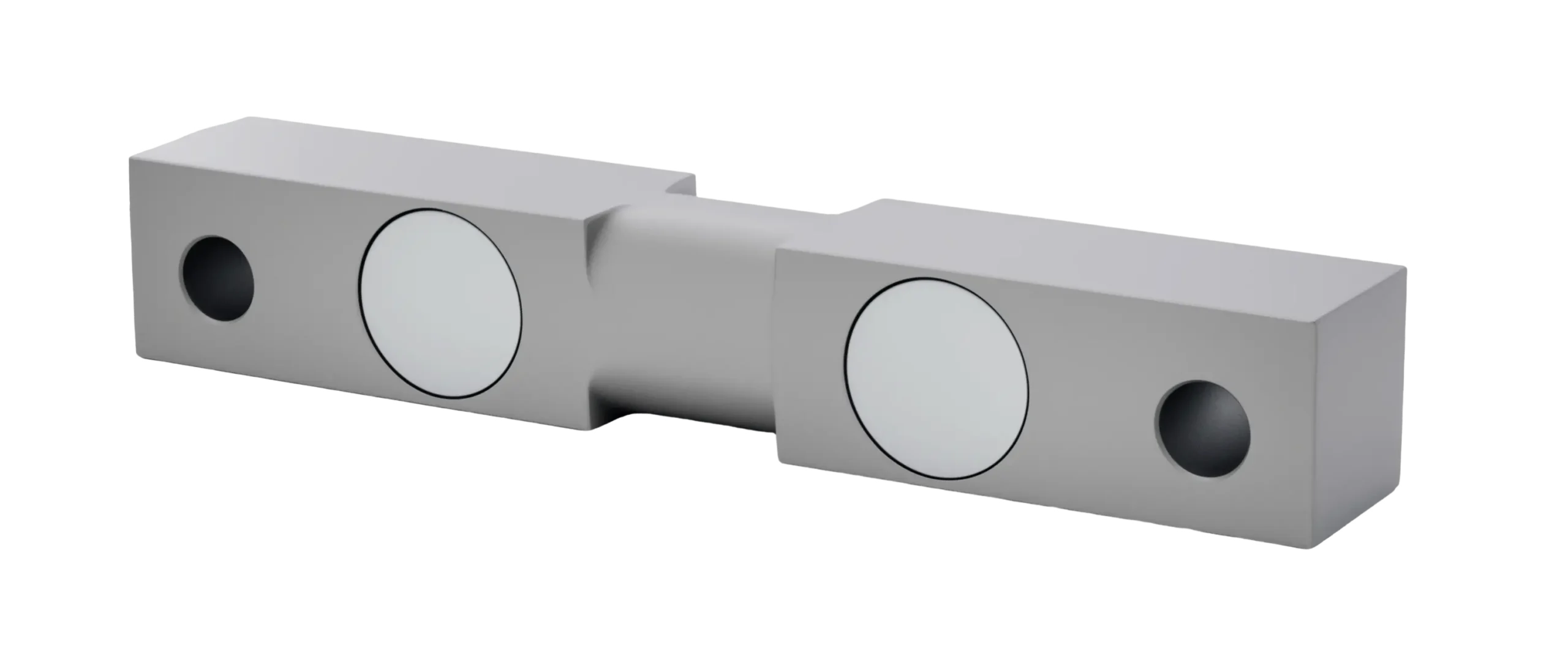
Shear beam against bending beam
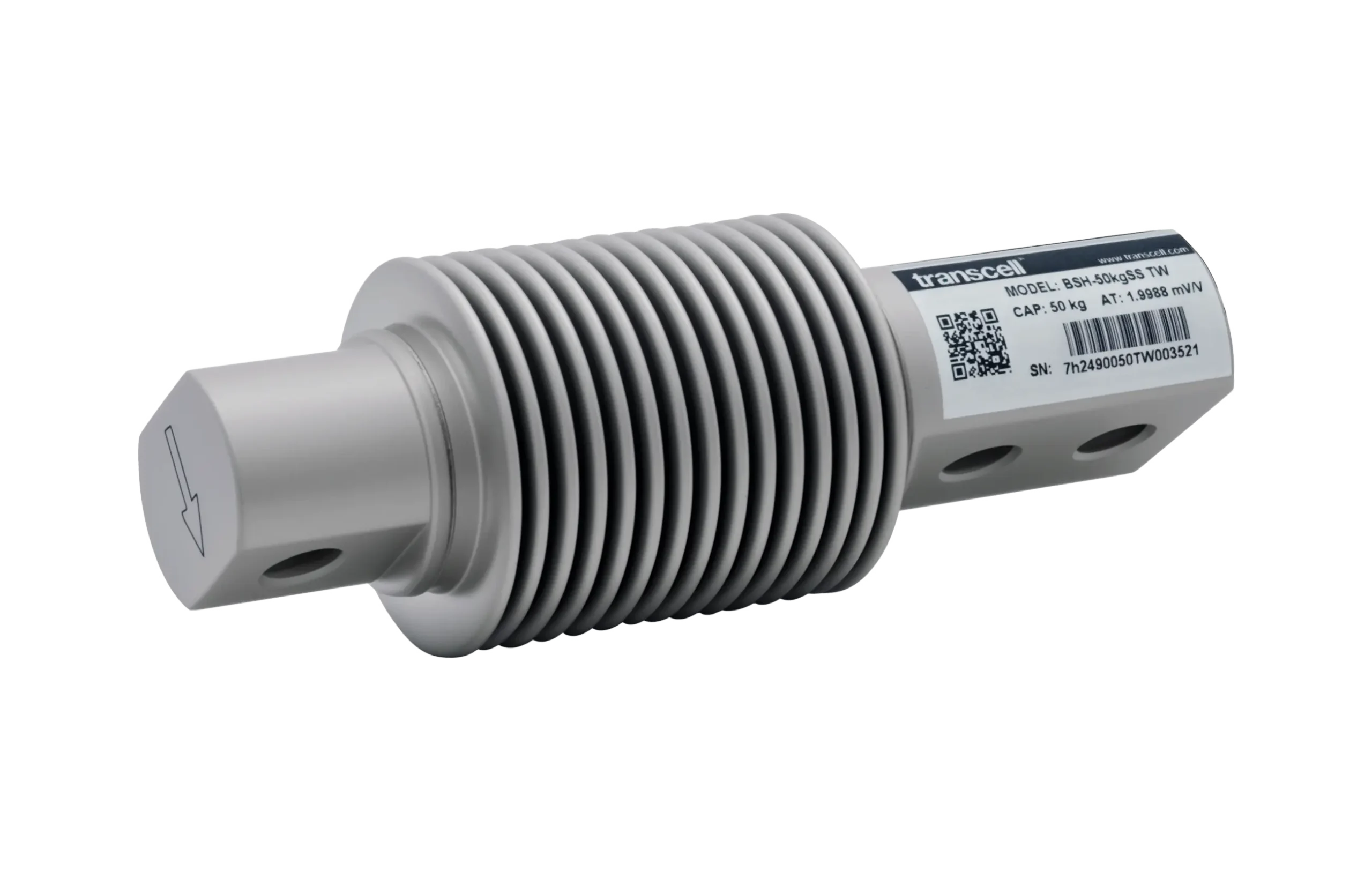
A bending beam gauges the top and bottom surfaces, where bending strain is largest. Its output is proportional to moment, so the distance from the mount to the load point is part of the calibration and the loading point has to stay where the design put it. Bending beams are consequently lighter-duty, tightly fixtured parts. Our BSH runs 50 to 300 kg and is exactly that.
A shear beam gives up some of the strain magnitude a surface-gauged beam enjoys, and gets back positional tolerance and a much stiffer section. That is the right trade above roughly a thousand pounds per corner, where nothing is going to hold the load point to a millimetre.