Skip to content
Free 2-Day Shipping For All Orders Nationwide. No Minimum PurchaseFree 2-day shipping, no minimum
Home / Shop / Load Cells / Load Cells for Chatillon and Lloyd Instruments

Load Cells for Chatillon and Lloyd Instruments

Designed, built and calibrated in-house.
Free shipping across the USA.

Built and calibrated in-house.Talk to an engineer

Decide

Not sure which one? Two ways to narrow it.

Find the part by its thread

You already own the machine, so the load is not the question. The hardware is. Search a size and we will name the models that take it, and the capacities they take it in.

The threaded holes it mounts through, and the rod ends, eye bolts and hardware that screw into them. Search any size. Our standard sizes narrow the answer below, and one we do not carry goes straight to an engineer as a custom build.

Every part, and the machine it fits

The compatibility table: which machine each part drops into, the original it replaces, and the capacities it is built in. Model names go to the product pages.

The replacement load cell reference.

What a drop-in replacement has to match before it reads at all, how to cross your original part number over, and what fitting one does to your calibration.

What drop-in means

A load cell the machine already knows.

A Chatillon tester or a Lloyd testing machine does not simply amplify whatever bridge is connected to it. Four separate things have to agree before a replacement reads at all, and capacity is only one of them.

Four interfaces, and all four have to match

The first is the electrical connection. The A1 Series for the Chatillon CS and CS2Plus ships with its required connector and electronics; the TC-TLC for the TCD testers ships with its required 15-pin connector. A load cell with flying leads has no way into either machine.

The second is what the machine expects to receive. The host reads the returning signal against the capacity it believes is fitted. Get that wrong and the machine still shows a number: a wrong one, in the right units, with no error raised. The third is the on-board electronics: these are not bare strain gauge bridges, and each A1 and TC-TLC carries the electronics the machine expects to find behind the connector. The fourth is mechanical, the mounting thread and the eye-end adapter that put the specimen in line with the load path.

Which is why a general purpose load cell of the right capacity will not do: a cable rather than the machine's connector, nothing behind that connector to talk to, threads chosen for rigging instead of a crosshead, and a full-scale output set by its own datasheet. That failure is worse than a dead channel, because a machine that reads something gets trusted and a machine that reads nothing gets investigated.
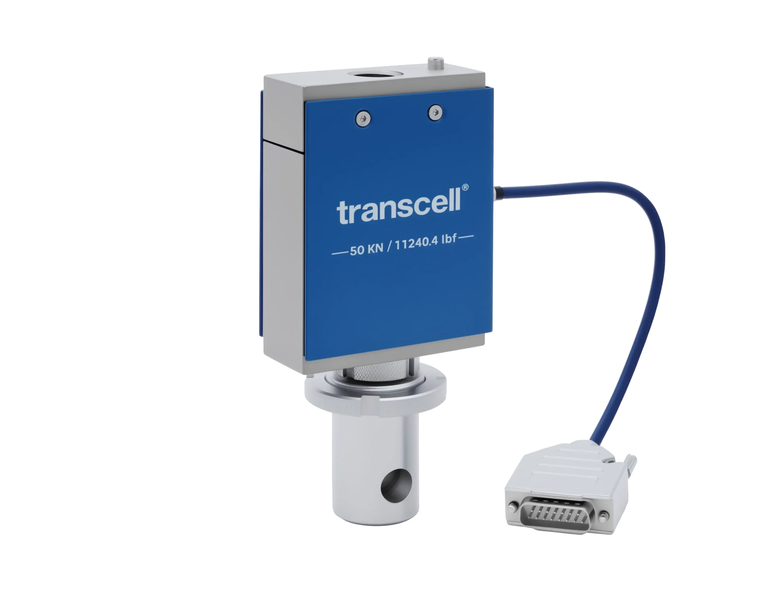
Transcell A1 Series replacement load cell for Chatillon and Lloyd Instruments testing machines

Go deeper

The two families of part on this page

The testing machine load cells, A1 Series and TC-TLC, are complete instruments. Each includes its connector and electronics, a padded carrying case and a 5/8in [15.8mm] diameter eye-end adapter (31.7mm [1 1/4in] on the Lloyd 20 kN to 100 kN units), and the Chatillon sheets specify them at an enhanced ±0.1% FS.

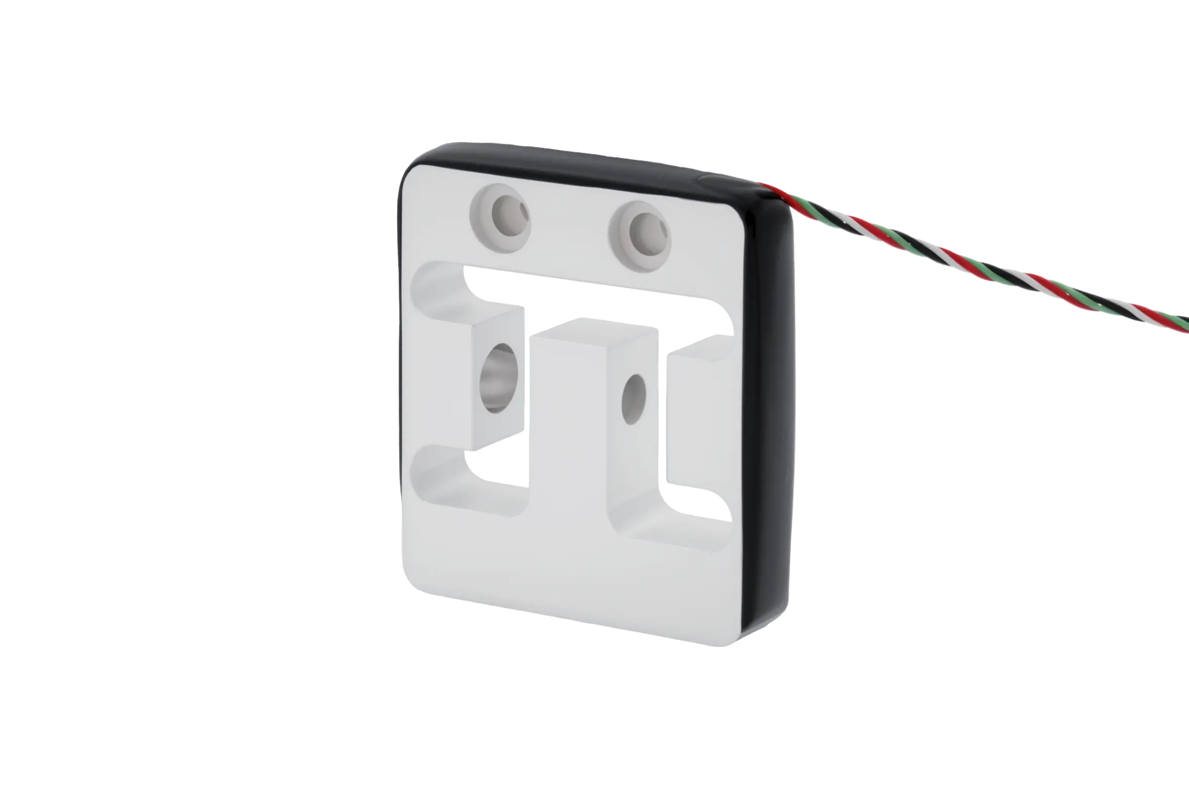
The force gauge repair kits, TS-DFS3 and TS-DFX, are service parts for a hand-held or stand-mounted gauge. The TS-DFS3 contains the load cell, the loading shaft, mounting screws and mounting pins; the TS-DFX contains the load cell, the loading shaft and the connection cable. Neither sheet publishes a nonlinearity figure, so none is quoted here; the sheets state capacity, loading shaft thread and material, and the product pages give the safe overload as 1.5× rated.

Enhanced safe overload, and where it stops

This is the one place a replacement genuinely beats the original. Both the A1 and the TC-TLC carry more safe overload than the design they replace. A 2 lbf A1 survives ±20 lbf, ten times its rating; the Chatillon range holds ten times from 2 to 200 lbf, and only the 500 and 1,000 lbf models drop to five, at ±2,500 and ±5,000 lbf. The Lloyd range repeats the pattern in newtons: ten times rated from 10 N to 1 kN, five times from 2.5 kN to 10 kN, three times from 20 kN to 50 kN, and standard safe overload of ±150 kN on the 100 kN unit, which the sheet calls out rather than leaving you to notice.

Safe overload is survival, not working range. It covers the specimen that lets go, the crosshead driven into a fixture, the operator who fits a 2 lbf load cell and pulls by hand. The reading during the event is not a measurement.
Matching

Your machine first. Then the capacity.

Nobody arrives here with a load in mind. They arrive with a machine and a part that has stopped reading, so the order of work is machine, then capacity, then crossover part number, and the third step is the one that catches people out.

Step one: find the machine

Lloyd Instruments testing machines take the A1 Series for an XLC or YLC. Chatillon CS and CS2Plus machines (CS225, CS1100 and CS2-225 among them) take the A1 Series for a CLC. The TCD110, TCD225 and TCD1100 take the TC-TLC; DFS-R-ND and DFS II-R-ND gauges take the TC-SLC; DFE3 and DFS3 gauges take the TS-DFS3 kit, DFX and DFX II the TS-DFX.

Step two: read the capacity off the old part

The original part number carries it. CLC-0050 is a 50 lbf load cell, TLC-0100 is 100 lbf, XLC-0250-A1 is 250 N. If the machine is being repurposed rather than repaired, choose the capacity you now need instead, from the list the machine supports.

Step three: check the crossover, not the digits

On the TC-TLC the numbering agrees: TC-TLC-0050 replaces TLC-0050. On the A1 it does not, because the same part IDs serve the Lloyd table and are numbered in newtons there. TC-OLP-0010-A1 is the 10 N unit for Lloyd and the 2 lbf replacement for CLC-0002. Read across the row.

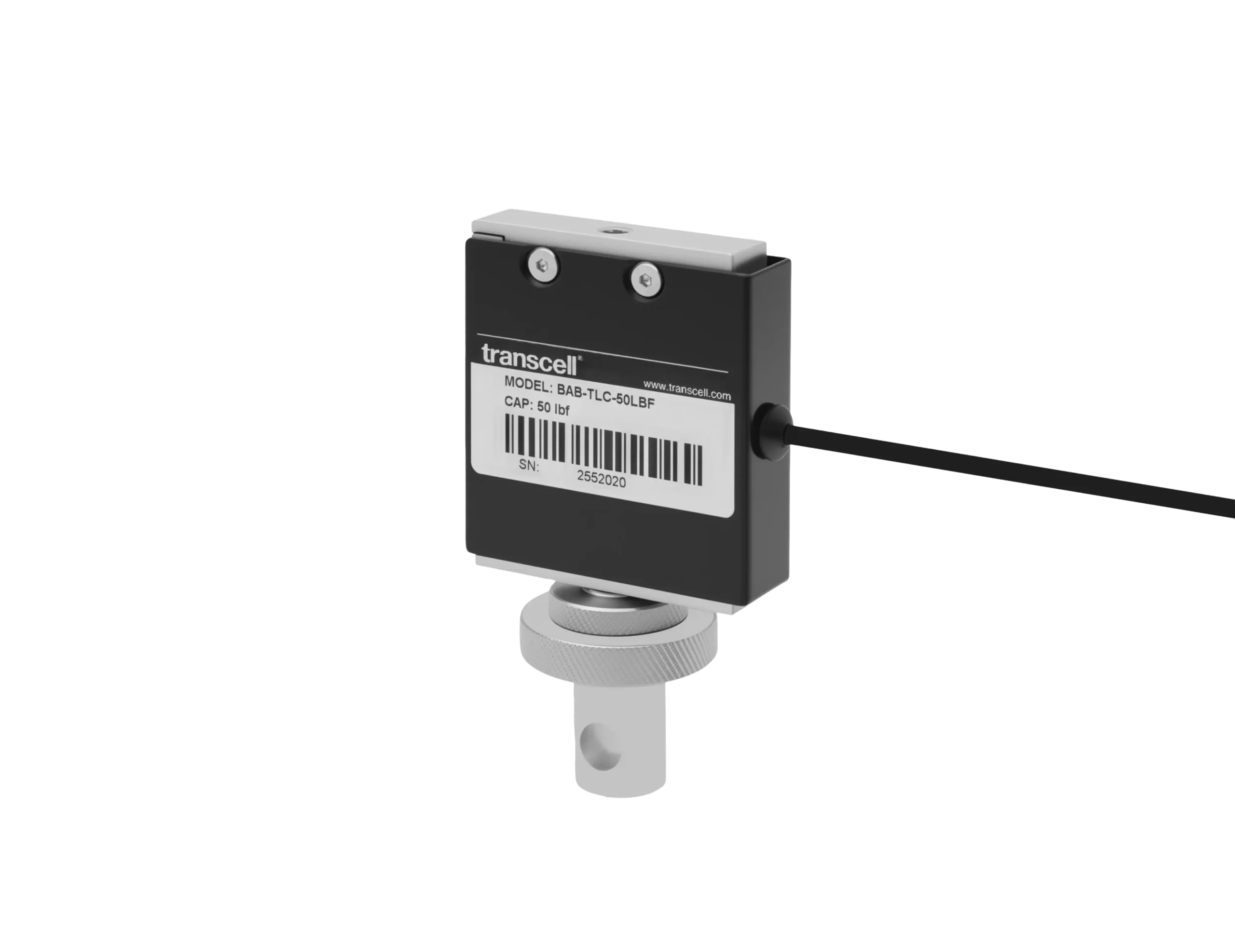
Transcell TC-TLC 50 lbf replacement load cell for Chatillon TCD series testers

Go deeper

The Chatillon CLC crossover, in full

Nine models: A1 part ID, the CLC it replaces, capacity, safe overload.

TC-OLP-0010-A1 · CLC-0002 · 2 lbf · ±20 lbf. TC-OLP-0020-A1 · CLC-04-5 · 4.5 lbf · ±45 lbf. TC-OLP-0050-A1 · CLC-0010 · 10 lbf · ±100 lbf. TC-OLP-0100-A1 · CLC-0020 · 20 lbf · ±200 lbf. TC-OLP-0250-A1 · CLC-0050 · 50 lbf · ±500 lbf.

TC-OLP-0500-A1 · CLC-0100 · 100 lbf · ±1,000 lbf. TC-OLP-1000-A1 · CLC-0200 · 200 lbf · ±2,000 lbf. TC-OLP-2500-A1 · CLC-0500 · 500 lbf · ±2,500 lbf. TC-OLP-5000-A1 · CLC-1000 · 1,000 lbf · ±5,000 lbf.

The Lloyd XLC and YLC crossover, in full

Fourteen models: capacity, safe overload, then the original with its Lloyd catalog code, often the only identification left once the capacity label has worn off.

10 N · ±100 N · XLC-0010-A1 (01/2360) or YLC-0010-A1 (01/3872). 20 N · ±200 N · XLC-0020-A1 (01/2950) or YLC-0020-A1 (01/3873). 50 N · ±500 N · XLC-0050-A1 (01/2361) or YLC-0050-A1 (01/3874). 100 N · ±1 kN · XLC-0100-A1 (01/2480) or YLC-0100-A1 (01/3875). 250 N · ±2.5 kN · XLC-0250-A1 (01/3048) or YLC-0250-A1 (01/3876).

500 N · ±5 kN · XLC-0500-A1 (01/2362) or YLC-0500-A1 (01/3877). 1,000 N · ±10 kN · XLC-1000-A1 (01/2419) or YLC-1000-A1 (01/3878). 2,500 N · ±12.5 kN · XLC-2500-A1 (01/2363) or YLC-2500-A1 (01/3879). 5,000 N · ±25 kN · XLC-5000-A1 (01/2464) or YLC-5000-A1 (01/3880). 10 kN · ±50 kN · XLC-10K-A1 (01/2365) or YLC-10K-A1 (01/3962).

The top four are XLC only. 20 kN · ±60 kN · XLC-20K-A1 (01/2417). 30 kN · ±90 kN · XLC-30K-A1 (01/2366). 50 kN · ±150 kN · XLC-50K-A1 (01/2367). 100 kN · ±150 kN · XLC-100K-A1 (01/2896).

The TC-SLC, and how it differs from the TC-TLC

The TC-SLC replaces the Chatillon SLC in DFS-R-ND and DFS II-R-ND gauges, and the store sells it from 2 to 10,000 lbf. It has its own sheet, and that sheet specifies an enhanced ±0.25% FS, not the TC-TLC’s ±0.1% FS. Through 1,000 lbf its safe overloads match the TC-TLC model for model, from ±20 to ±5,000 lbf.

The sheet carries on above that: ±10,000 lbf safe overload on the 2,000 lbf model, ±15,000 lbf on the 5,000 and ±30,000 lbf on the 10,000. The thread steps with capacity: 1/4in-28F through 200 lbf, 1/2in-20F from 500 to 2,000 lbf, and 3/4in-16F on the 5,000 and 10,000 lbf models.

Fitting and calibration

Eye ends, threads, and one calibration.

Fitting is the short part. What decides whether the machine is trustworthy afterwards is the load path through the adapter, and the calibration you do once the load cell is in place.

The mechanical interface, by capacity

Every A1 for the Chatillon CS and CS2Plus, and every TC-TLC, includes a 5/8in [15.8mm] diameter eye-end adapter. Across the Lloyd range the adapter changes with capacity: 15.8 mm aluminium from 10 N to 250 N, 15.8 mm stainless from 500 N to 10 kN, and 31.7 mm [1 1/4in] stainless on the four largest, 20 kN through 100 kN.

The mounting thread steps with it. M12×1.75 covers everything from 10 N to 10 kN, M20×2.5 takes over at 20, 30 and 50 kN, and the 100 kN unit is M24×2. Check the thread against the crosshead before ordering a capacity step up, because the step that raises the range also changes the interface.

On the repair kits the equivalent part is the loading shaft. Most of the TS-DFS3 and TS-DFX range takes a #10-32 shaft; the larger models, the 200 lbf among them, take 5/16in-18. The TS-DFS3 also brings the mounting screws and pins that hold the load cell in the gauge body, so the fasteners disturbed on the way in are replaced rather than reused.

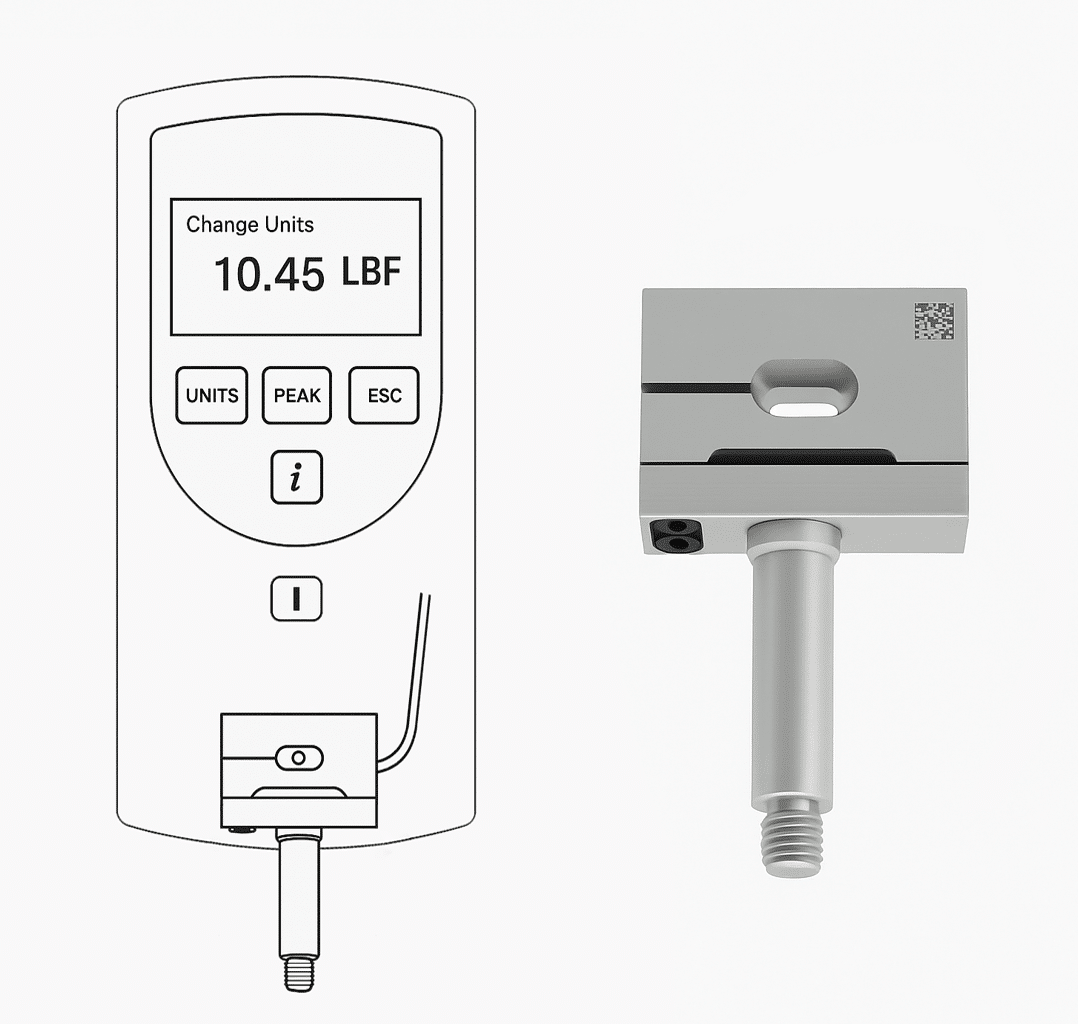
Transcell TS-DFS3 load cell repair kit for Chatillon DFE3 and DFS3 force gauges

Go deeper

Calibrate to the machine, not to the load cell

The A1 and TC-TLC sheets say the same thing in the same words, and it is the most useful sentence on either: to surpass the enhanced ±0.1% FS accuracy specification, the load cell should be calibrated to the specific test machine it is being used with.

That figure is a property of the load cell in isolation. Once it is in a frame, the frame's compliance, the adapter, the grips and the machine's electronics all sit in the measurement chain, and calibrating the assembled system absorbs them into one correction. Fit, then calibrate, then record: a part that reads immediately makes it tempting to skip the middle step, and what it gives you beforehand is the load cell's accuracy rather than the machine's.

The adapter and the case are both part of the job

Everything the specimen does passes through the adapter thread. Wind it fully home so the shoulder seats, and align the specimen so the pull is axial: a load cell built for tension and compression along one axis reads side load as though it were force, and no calibration removes it. Do not substitute a workshop bolt: a close-but-wrong pitch binds, takes up load on a few engaged threads and damages a tapping in a part that is not sold separately.

Each A1 ships in a protective carrying case lined with anti-static foam against electrical and mechanical shock, labelled outside with capacity and model number. Keep the load cell in it between jobs: a knock off a bench is a zero shift nobody sees until something else disagrees with the machine, and an unlabelled load cell in a drawer is one nobody trusts.

Applications

What these machines actually do.

The load cell measures; the machine around it decides what the measurement is for. These are the tests that keep Chatillon and Lloyd frames in service long enough to need a replacement.

Materials testing

The Lloyd frames are materials testing machines, and the 10 N to 100 kN spread reflects it: film and foil at the bottom of the range, structural and metallic specimens at the top. One frame often covers both, with the load cell changed to suit the specimen, which is why the carrying case and the capacity label earn their keep.

Test and measurement

Quality control and production line force verification

Chatillon CS, CS2Plus and TCD testers, and the DFE3, DFS3, DFX and DFX II gauges, are the everyday QC instruments: cap and closure removal, connector insertion and withdrawal, actuation force on switches and buttons, recorded against a pass-fail limit. A gauge on a line is a measuring instrument with a hard life, and repair kits exist because the load cell takes the abuse while the display, the memory and the calibration record stay in the gauge.

Production automation

Spring testing, peel and tear

Spring rate needs force at a controlled displacement, so it lives on a motorised stand rather than a hand gauge. Peel, tear and seal strength run through the same frames at low capacities, where the 2 and 10 lbf load cells earn their overload margin: the specimen fails suddenly and the crosshead is still moving.

Transcell TS-DFX replacement load cell for Chatillon DFX and DFX II force gauges

Before you order one

The questions worth asking.

Will this work in my machine?

If the machine is on the fitment list above, yes, and without modification: each part is built as a drop-in for one named original, and each testing machine load cell arrives with the connector and electronics that machine expects. Match the original part number rather than the capacity.

Is it as accurate as the original?

The A1 Series and the TC-TLC are specified at an enhanced ±0.1% FS, and both sheets describe the design as improving on the original in measurement performance as well as in safe overload: a 2 lbf A1 survives ±20 lbf. To do better than the ±0.1% FS figure, calibrate the load cell to the machine it is fitted to.

What if my machine model is not listed?

Work from the load cell instead of the machine. If the part fitted is an XLC, YLC, CLC, TLC or SLC, the crossover tables identify the replacement by original part number whichever frame it sits in. If it is none of those, the machine is outside this range, and a general purpose load cell of the same capacity will not substitute: connector, electronics and mounting thread all have to match, not just the rating.

Do I need to recalibrate after fitting?

Plan on it. The part is drop-in and reads as soon as it is connected, but published accuracy is a load cell specification and your machine is a system. Calibrating to the specific machine is what the A1 and TC-TLC sheets ask for, and what an audited QC process expects recorded against the swap.

What is in the repair kit?

The TS-DFS3 for DFE3 and DFS3 gauges contains the load cell, the loading shaft, mounting screws and mounting pins, in seven capacities from ±2 to ±500 lbf, steel except the 2 lbf, which is aluminium. The TS-DFX for DFX and DFX II contains the load cell, the loading shaft and the connection cable, in ±10, ±50, ±100 and ±200 lbf, all steel. Loading shafts are #10-32 or 5/16in-18 by model.

We Make Your Challenge Our Business

Tell us what it has to do and we’ll tell you what it takes.

Contact Us