
Skip to content
Free 2-Day Shipping For All Orders Nationwide. No Minimum PurchaseFree 2-day shipping, no minimum
Home / Shop / Load Cells / Inline Threaded Load Cells

Inline Threaded Load Cells

Designed, built and calibrated in-house.
Free shipping across the USA.

Built and calibrated in-house.Talk to an engineer

Decide

Not sure which one? Two ways to narrow it.

Size it for me

Give us the load and, if it is fixed, the thread you have to screw into. We will name the exact model, or the TCM that replaces the FUTEK part you are holding.

The heaviest load the load cell sees in normal use, in tension or compression.

Search the thread you have to screw into, or the FUTEK FSH040xx part you are replacing. Every TCM is a published drop-in for one.

Pre-filled with a 2,000 lb example. Type over it. We add 1.25× headroom, then name the smallest TCM model that carries it. Every model is 150% safe overload or better, so there is no overload question to ask.

Every TCM model at a glance

All eight orderable models on one screen: capacity, thread, safe overload and the FUTEK part each one replaces. Model names go to the product pages.

The inline load cell engineering reference.

How a threaded link reads force in both directions, how to size one against a capacity you will not regret, and how to mount it so that alignment does not quietly corrupt every number it gives you.

How they work

One axis. Nothing else.

An inline threaded load cell is the simplest load path a sensor can have. A male thread at each end, the force running straight down the axis between them, and a strain-gauged element in the middle reading it. Nothing is cantilevered and nothing is offset, which is why the body can be barely an inch across and still carry ten thousand pounds.

Two threaded ends, one load path

The body is machined from 17-4PH stainless steel with a male thread at each end. One end is the fixed end and the other is the active end; the load travels in a straight line from one to the other, through a section of the body thin enough to strain measurably under it.

Foil strain gauges bonded to that section change resistance as it stretches or compresses, and four of them wired as a Wheatstone bridge turn that into a millivolt signal proportional to load. Pull on the load cell and the signal goes one way; push on it and the same part sends the signal the other way, which is why one model covers tension and compression with no change of hardware.

Rated output is 2 mV/V across the whole series. The construction is sealed to IP64, which handles dust and splashing in a machine enclosure, but it is not a washdown or submersible rating.
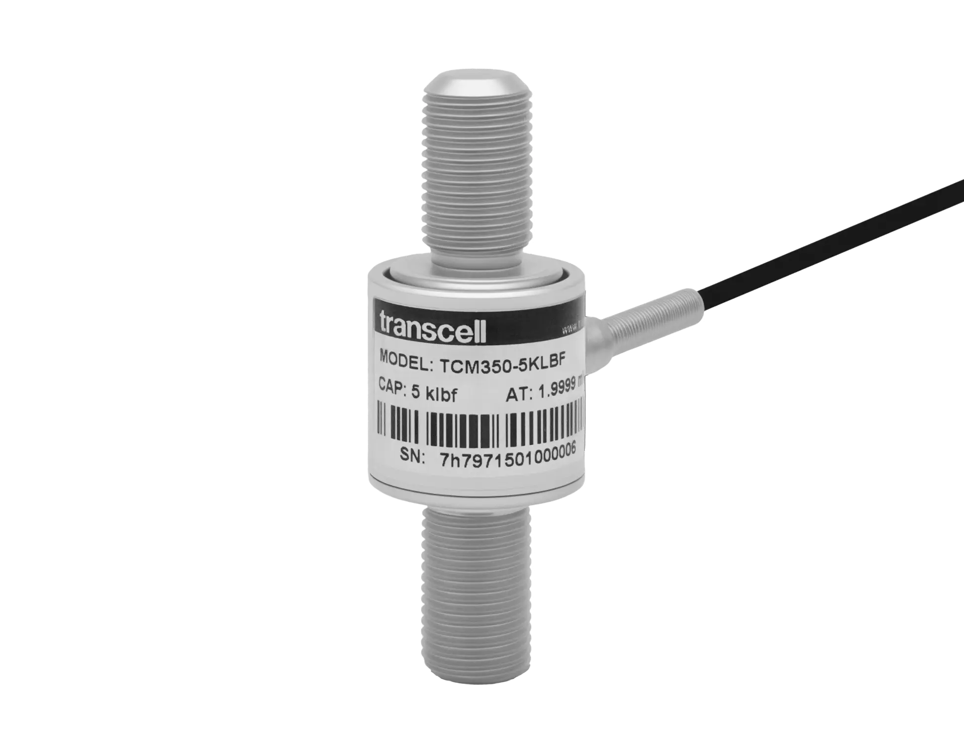
Transcell TCM350 inline threaded load cell with male threads at both ends

Go deeper

What 2 mV/V actually gives you

Rated output is a ratio, not a voltage: the load cell returns 2 mV for every volt of excitation at full capacity. At the rated 10 V excitation, a TCM at full load returns 20 mV. Maximum excitation is 15 V, which would give 30 mV.

Bridge resistance is 410 Ω input and 350 Ω output, so any instrument that reads a standard 350 ohm bridge will read these. Insulation resistance is ≥5 GΩ at 50 VDC.

The integrated cable is 10 ft (3 m) of 4-conductor 28 AWG with a shield. Four conductors means there are no sense lines, so keep the run short or account for lead resistance in calibration, and calibrate the system with the cable that will be installed.

Both directions, one part number

Every capacity in the series is specified as a ± figure. A TCM350-5KLBF is ±5 klbf: five thousand pounds of pull and five thousand pounds of push, from the same load cell, with the same calibration.

That matters more here than on most geometries, because an inline load cell usually sits in an actuator or a test frame where the load genuinely reverses. A cylinder that pulls on the extend stroke and pushes on the retract stroke needs one load cell, not two.

The zero sits in the middle. Zero balance is ±1% RO, so expect a small offset at no load and null it in the instrument.

Where this series sits on accuracy

Nonlinearity and hysteresis are ±0.25% of full scale, and non‑repeatability is ±0.05%. That last figure is the one to read closely: the load cell repeats itself tightly, which is what closed-loop machine control actually depends on.

It is worth being plain about the comparison. Our S-beams are ±0.02% to ±0.05% nonlinearity, five to ten times tighter, and some are NTEP certified. Nothing in the TCM series is certified, and none of it is intended for buying and selling by weight.

What you are buying instead is a load cell that fits inside a machine, threads directly into the load path, and reads force in both directions with excellent repeatability. If the number has to be a legal weight, use an S-beam.
Sizing

Capacity and headroom. Size it once.

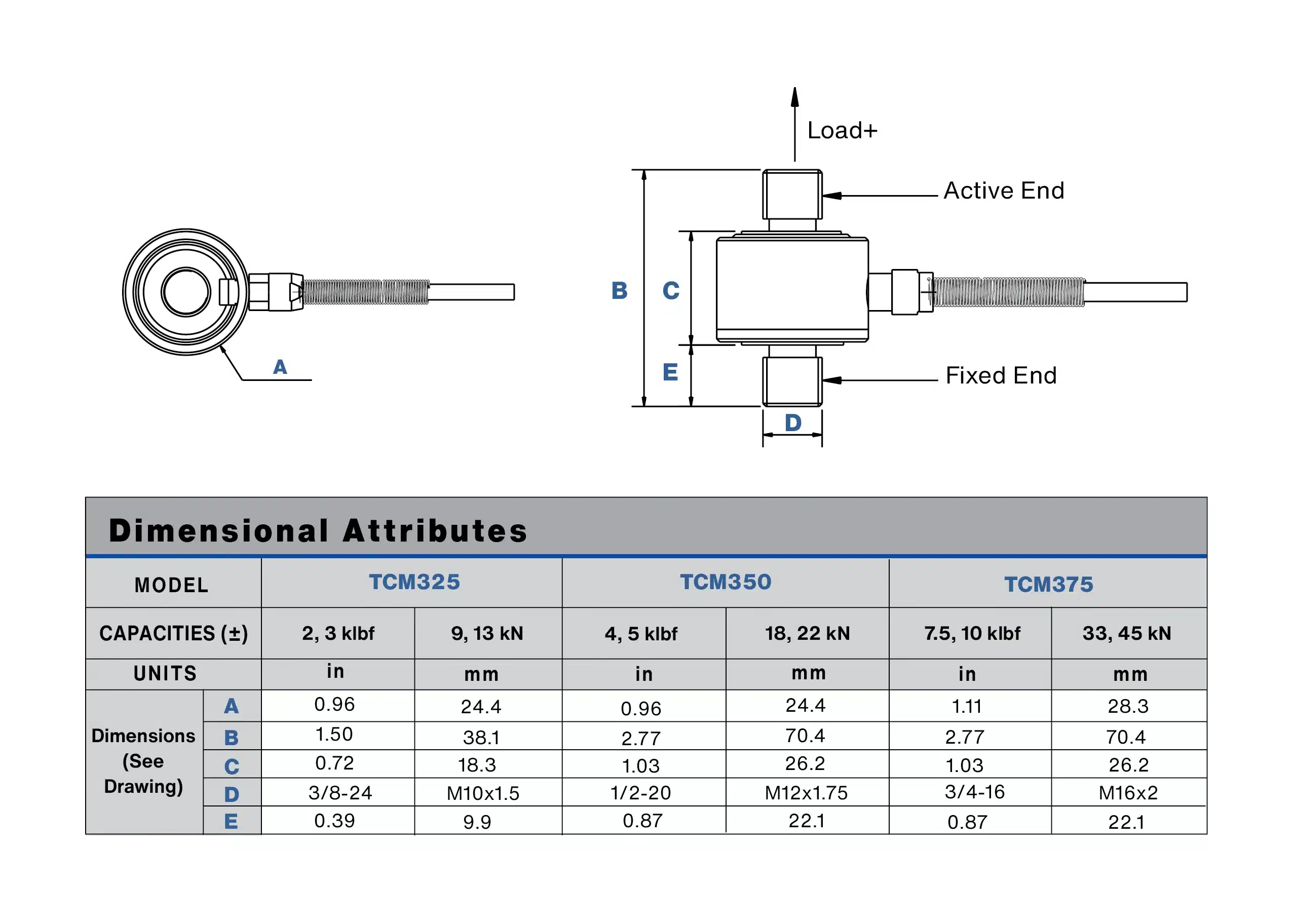
Three bodies cover the series, and each one carries an imperial thread and a metric thread over roughly the same capacity. Choose the body by load first, then take whichever thread your hardware needs.

BodyCapacitiesThreadsSafe overloadTypical use
TCM3252 and 3 klbf, 13 kN3/8″-24, M10×1.54.5 klbf, 19.5 kN Actuator force feedback, small test frames, robotic end effectors
TCM3505 klbf, 22 kN1/2″-20, M12×1.757.5 klbf, 33 kN Cable and rope tension, press monitoring, component fatigue rigs
TCM3757.5 and 10 klbf, 45 kN3/4″-16, M16×215 klbf, 67.5 kN Structural test, suspension and damper testing, heavy actuation

Size so the working load lands between 30% and 80% of rated. Below 30% you are spending resolution you paid for; above 80% there is nothing left for the peaks. Safe overload is 150% of rated across the series, with the TCM325-2KLBF at 225% and the TCM375-7.5KLBF at 200%. That is protection against a mistake, not headroom to design into.

Mounting

Everything off-axis is error.

An inline load cell becomes a structural link in your machine. It reads the force along its axis honestly, and it has no way to tell you about the bending moment, side load or torque you also put through it. Those do not cancel out. They arrive as signal.

Four things that decide whether the number is true

Full thread engagement. Engage the mating thread along its whole length, and make sure the fitting does not bottom out before it seats. A partly engaged thread concentrates stress in the first few turns and moves the effective load point.

Never torque through the body. Hold the flats when you tighten anything onto either end. Using the load cell itself as the wrench puts torsion straight through the element and can shift the zero permanently.

Rod ends at one end, at least. A spherical rod-end bearing lets the load line find itself instead of forcing the load cell to absorb the misalignment as a bending moment. On a test frame where both anchor points are fixed, use them at both ends.

Support the cable, not from the load cell. Strain-relieve the integrated cable to structure near the load cell so movement never pulls on the gland. IP64 covers dust and splashing; it does not cover a hose, immersion, or a damaged entry.

TCM series dimensional drawing showing the active end, fixed end and male thread at each end

Go deeper

Why alignment matters more here than on an S-beam

An S-beam has a comparatively long, compliant body between its two threaded connections, and that compliance absorbs a degree of angular misalignment before it becomes error.

An inline load cell is short and stiff by design: the whole point is that it fits in a gap an S-beam cannot. Stiffness that buys you the package size also means a misaligned load path has nowhere to go except into the element as a bending moment.

In practice: an S-beam mounted a couple of degrees out will read slightly high and be mostly forgivable. An inline load cell mounted the same way will read wrong and drift with every stroke as the geometry works.

Jam nuts, preload and setting the length

Set the working length with the mating hardware, then lock it with a jam nut against the fitting rather than against the load cell body wherever the geometry allows.

Preload is not a problem in itself: a load cell that reads ± is happy sitting at a non-zero static load. What matters is that you null the instrument after everything is torqued to its final state, so the zero you work from includes the preload.

If the assembly is going to be taken apart and rebuilt regularly, re-null it each time. Repeatability of ±0.05% is a property of the load cell, not of your fastener stack.

Applications

Where a threaded link is the only thing that fits.

These go where there is already a rod, a linkage or a cable, and no room for a load cell that needs its own mounting plate.

Typical installations

Actuator force feedback. Threaded between a cylinder rod and its clevis, reading push and pull on the same part so a controller can close the loop on force rather than position.

Materials and component testing. In the load train of a small tensile or fatigue frame, where the ±0.05% repeatability matters more than absolute accuracy because the interesting number is the change between cycles.

Cable, rope and chain tension. Spliced into a tensioning turnbuckle with rod ends at both sides, so the load cell measures the line and nothing else.

Test and measurement

Suspension and damper testing. The TCM375 at 10 klbf covers most automotive damper work, in a body short enough to fit inside an existing test fixture.

Robotic end effectors and assembly. Press-fit and insertion force monitoring, where the whole sensor has to disappear into the tool.

Production automation

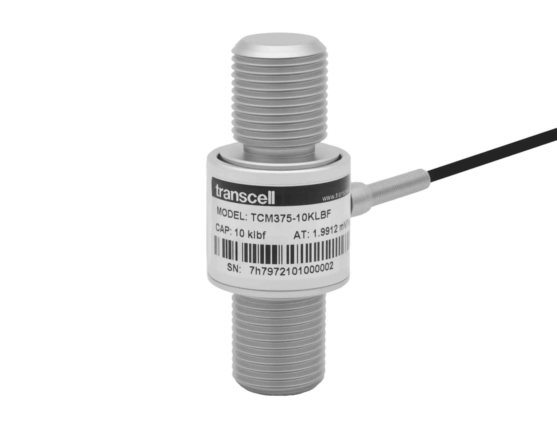
Transcell TCM375 inline threaded load cell

Questions

The ones we actually get asked.

Will this really replace my FUTEK FSH040xx?

That is what the series was built for, and every model publishes the part it replaces: FSH04009 and FSH04006 for the TCM325 in 3/8-24, FSH04007 for the metric TCM325, FSH04078 and FSH04080 for the TCM350, and FSH04081, FSH04082 and FSH04084 for the TCM375. Capacity, thread and form factor match, with improved accuracy. Search the FUTEK number in the sizing tool above and it will name the Transcell part.

Can one load cell read tension and compression?

Yes, and that is the normal way to use them. Every capacity is a ± figure, so a ±5 klbf load cell carries 5,000 lb of pull and 5,000 lb of push on one calibration. Expect a small zero offset, up to ±1% of rated output, and null it in your instrument once everything is torqued down.

Are these legal for trade?

No. Nothing in the TCM series is NTEP certified, and at ±0.25% of full scale it is not intended for buying and selling by weight. If the reading is a legal weight, the BSS S-beam is certified from 250 lb to 2,500 lb. If the reading is a force inside a machine, this series is the right tool.

What thread do I get, and can you cut a different one?

Six as standard: 3/8-24, 1/2-20 and 3/4-16 imperial, M10×1.5, M12×1.75 and M16×2 metric, male at both ends. Thread form is one of the more straightforward things to change on an inline body, so if you need something else, ask. The sizing tool above will route you to an engineer if you search a thread we do not stock.

What else do I need besides the load cell?

An instrument that takes a mV/V bridge input: an indicator, a transmitter, or a signal conditioner if a PLC or a data acquisition system is reading it. The load cell has a 4-conductor cable with no sense lines, so keep the run short and calibrate the system with the cable you will install.

How far past rated can it go?

Safe overload is 150% of rated across most of the series, with two models higher: the TCM325-2KLBF is protected to 4.5 klbf, which is 225%, and the TCM375-7.5KLBF to 15 klbf, which is 200%. Treat all of it as protection against an accident rather than as capacity you can plan to use.

We Make Your Challenge Our Business

Tell us what it has to do and we’ll tell you what it takes.

Contact Us