
Skip to content
Free 2-Day Shipping For All Orders Nationwide. No Minimum PurchaseFree 2-day shipping, no minimum
Home / Shop / Load Cells / Double-Ended Beam Load Cells

Double-Ended Beam Load Cells

Designed, built and calibrated in-house.
Free shipping across the USA.

Built and calibrated in-house.Talk to an engineer

Decide

Not sure which one? Two ways to narrow it.

Size it for me

Give us the load you actually need to weigh or pull. We will size the load cell against it and name the model, using the same rule our engineers use.

The heaviest load on the load cell in normal use, including anything hanging with it.

The threaded holes it mounts through, and the rod ends, eye bolts and hardware that screw into them. Search any size. Our standard sizes narrow the answer below, and one we do not carry goes straight to an engineer as a custom build.

Pre-filled with a 1,000 lb example. Type over it. We add 1.25× headroom, then match the nearest rated capacity in a family that meets the rest of your answers. Genuine shock and impact wants more than either: send us the details and we will size it properly.

The double-ended beam engineering reference.

Why the load arrives in the centre, what the rocker mount is actually for, and the installation mistake that makes an accurate load cell read wrong.

How they work

Supported at both ends. Loaded in the middle.

A double-ended beam is the mirror image of a single-ended shear beam. Rather than clamping one end down and hanging the load off the other, both ends are held down and the load arrives at the centre. That reversal is the whole of the geometry.

Two shear cavities, one either side of the load

A shear beam is machined with a blind cavity bored in from each face, thinning the section to a web with heavy flanges above and below. That web carries almost pure shear, and gauges bonded at ±45° to the neutral axis read it directly. Shear strain is constant along the web, so the output does not follow the moment arm the way a bending beam's does.

A double-ended beam has two of those cavities, one on each side of the centre load point. Load applied at the centre divides and travels outward to the two supports, so each web carries half of it. The bending the two halves produce is equal and opposite about the centre, and the four gauges are wired so that what is left of it cancels in the bridge. What reaches the output is the vertical shear and nothing else.

The payoff is capacity in a short body: each end reacts half the load rather than the whole of it plus a reaction moment. The cost is mounting: two supports and a centre bearing instead of one flat face. The DBS covers 2,500 to 75,000 lb across nine stocked capacities in three body sizes, from $550.
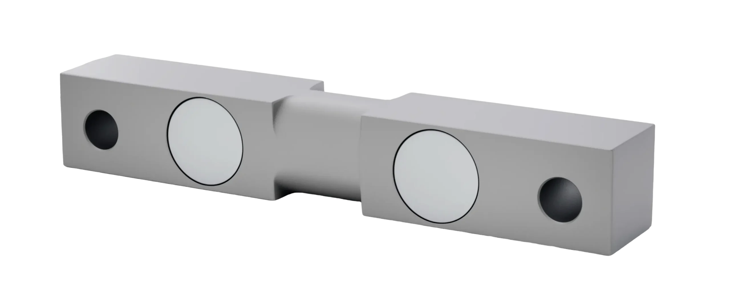
Transcell DBS Series double-ended beam load cell showing the shear cavity either side of the centre load point

Go deeper

Why shear, and not bending, at this size

Bending strain grows with the distance from the load to the gauges, which is workable where a bolted platform fixes the loading point and a liability at tens of thousands of pounds, where the load arrives through a bearing whose contact point shifts as the structure moves.

Shear strain does not vary along the web, so the reading survives that wandering. Tolerance of an imperfect load path, not raw accuracy, is why heavy weighing is built on shear geometry, though the accuracy is there too, at ±0.03% of rated output for nonlinearity, hysteresis, repeatability and creep after 30 minutes.

Alloy steel, nickel plating, and what the datasheet does not claim

The body is alloy steel with a nickel-plated finish for corrosion protection. That is a coating, not a hermetic seal, and the datasheet quotes no IP rating, so outdoors the water management belongs to the pit, the conduit and the junction box.

Temperature is specified twice and the two figures differ. The safe range is -10 °C to +70 °C; the compensated range, over which output and zero each drift no more than 0.002% per °C, is only -10 °C to +40 °C (14 °F to 104 °F). Above that the load cell keeps working and stops being characterised, which matters on a sun-heated deck.
Sizing

Divide the load. Then check the worst case.

Capacity per load cell is not the gross rating divided by the count. It is whatever the worst concentration of load puts into the most heavily loaded pair of supports, and that number is always the larger one.

What each load cell actually carries

Start with the dead load. The deck and the frame sit on the supports before anything is weighed, and on a heavy structure that share is substantial. It consumes rated capacity and does not come back.

Then stop dividing evenly. A load concentrated over one pair of supports puts far more than its proportional share into that pair, and the worst case is rarely the heaviest total. It is a heavy concentration sitting at one end. Size on that case, and size every position identically so the installation stays interchangeable.

Then leave headroom, but not too much. Aim for the normal maximum between about 30% and 80% of rated capacity; work lower than that and zero balance, specified at ±1% of rated output, becomes a large share of a small reading. The 150% safe overload is survival, not working range: what the load cell read during the event was not a measurement.

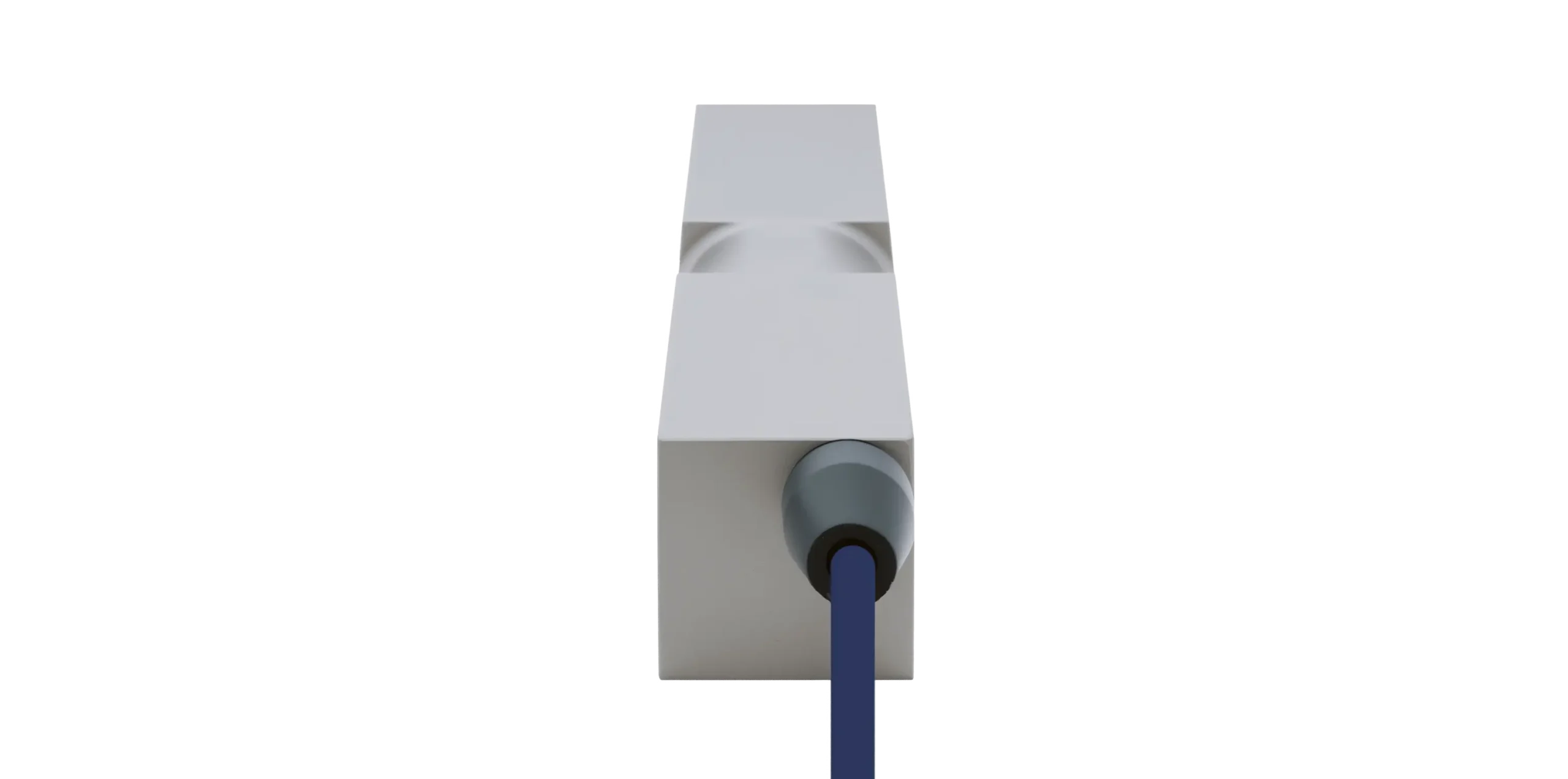
Transcell DBS double-ended beam load cell, end view with the cable gland

Go deeper

Paralleling several of them does not add signal

A summing junction box parallels the outputs, and parallel outputs average. Eight load cells under a deck do not produce eight times the signal: at full system capacity the box still delivers the rated 3.0 mV/V, which at the rated 10 V excitation is 30 mV for the whole scale, however many sit under it. Asking the indicator for more divisions than that span supports adds digits, not information.

What does change is the load on the excitation supply. Input impedance is 775 ohm ±20 ohm, so eight in parallel present roughly 97 ohm and four about 194 ohm. Check that against the indicator's minimum bridge resistance, and keep excitation at or below the 15 V maximum. Corner trimming happens in the box, and has to be redone whenever a load cell is replaced.

The nine stocked capacities, and the wider series

The store sells 2,500, 3,000, 5,000, 10,000, 20,000, 25,000, 30,000, 50,000 and 75,000 lb. The datasheet series is wider: it is specified from 1,000 lb, and 1,000, 1,500, 2,000 and 15,000 lb appear on the sheet without being stocked. Those are built to order.

Mounting

The mount is half the specification.

A double-ended beam bolts down at both ends through its mounting holes and takes the load at the centre. Where the structure above it moves, a rocker or link at the centre lets it move and then puts it back. Build that wrong and the load cell stays accurate while the scale does not.

Self-checking and link suspension

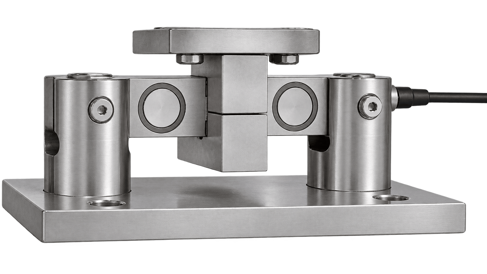
In a self-checking mount the load cell sits in a pair of end supports and the structure bears on the centre through a rocker pin, a short column with crowned or spherical ends. Push the deck sideways and the pin tilts, which raises the deck slightly; gravity then pushes it back to centre. The mount restores itself, which is where the name comes from, and nothing has to slide for it to do so.

A link suspension mount reaches the same result by hanging: the load cell hangs on a link at each end and the load hangs from the centre, so the assembly swings and self-centres like a pendulum. Either way the load cell sees one vertical force at one point, and the structure is free to grow and shrink underneath it.

Transcell DBS double-ended beam load cell seated in its mount, loaded through the centre

Go deeper

Why a rigid joint at the centre reads wrong

Bolting the ends down is correct. Bolt the deck hard to the centre as well, on a structure that moves with temperature, and the load cell stops being a sensor under a structure and becomes a member of it. When the deck expands it cannot slide, so the growth is reacted as a horizontal force at the ends. That force acts at a different height from the shear webs, so it arrives as a moment, and it is not symmetric (one end always grips harder than the other), so the bridge does not cancel it.

The result is not a broken load cell. It is a scale that zeroes first thing and reads high in the afternoon, does not return to zero after a heavy load has sat on it, and cannot be calibrated straight because the error is not constant. Every load cell in it tests fine on the bench.

The support span is part of the calibration

The load cell is characterised with its supports at defined positions and the load at the centre between them. Move the supports inboard or outboard and the geometry between the reaction points and the gauged webs changes, and so does the output at a given load. Nothing warns you: the scale still calibrates, to a span it was not certified on. Use the mounting hardware designed for the load cell rather than supports fabricated to fit an existing frame, and before accepting the installation check that both end supports are level and coplanar, that neither is twisted relative to its partner, and that the centre bearing sits square.

Check rods, bumpers and the clearance nobody sets

A self-checking mount handles small movement, not a vehicle braking on the deck or a vessel being knocked, so the structure gets check rods and bumpers to limit travel. Their job is to carry horizontal force at the limit of movement and no vertical load at all, ever.

Set the clearance with the structure on the load cells and loaded, not empty and not on the bench. A bumper that touches all the time is a load path around the load cell, and the share of the weight it steals changes with temperature. It is the second most common reason a heavy scale will not hold calibration.

The cable, the box and the ground

The connection is four-wire (red and black for excitation, green and white for signal) with no sense lines, so lead resistance sits inside the calibrated system. Never shorten one: in a paralleled installation that changes the load cell's share against its neighbours, and the corner trim will fight you. Order the length that reaches the box with a service loop, and strain-relieve to the foundation rather than to the moving structure.

Outdoors, fit a grounding strap across the mount so welding current and lightning surge have a path that is not the strain gauge bridge. Insulation resistance is specified at ≥5,000 M ohm at 50 V DC, and that is the measurement to repeat when a scale drifts after rain.

Applications

Where double-ended beams end up.

Wherever the load is heavy and the structure is large enough to move.

Vehicle and rail weighing

The standard geometry for a weighbridge deck and for rail weighing: the deck is long, it expands, and the load rolls across it. A rocker mount absorbs the movement and re-centres between weighments, and the shear webs tolerate a contact point that never lands twice in the same place. The upper capacities, 50,000 and 75,000 lb, exist for that work.

Heavy hoppers, tanks and vessels

Under a vessel leg the load cell has to stay accurate while the vessel grows with the temperature of its contents and while pipework pulls on it. The symmetric load path rejects that side force and the mount takes the expansion. What neither rescues is rigid plumbing, which is a second load path in its own right.

Grain silo and hopper weighing

Batching, warehouse and inventory scales

The datasheet names warehouse and inventory scales and batching systems, and the reason is repeatability rather than capacity: a batching sequence weighs the same nominal quantity thousands of times, so the ±0.03% figures for repeatability and creep matter more than the absolute number. The stocked capacities from 2,500 lb serve that work.

Pallet scale systems

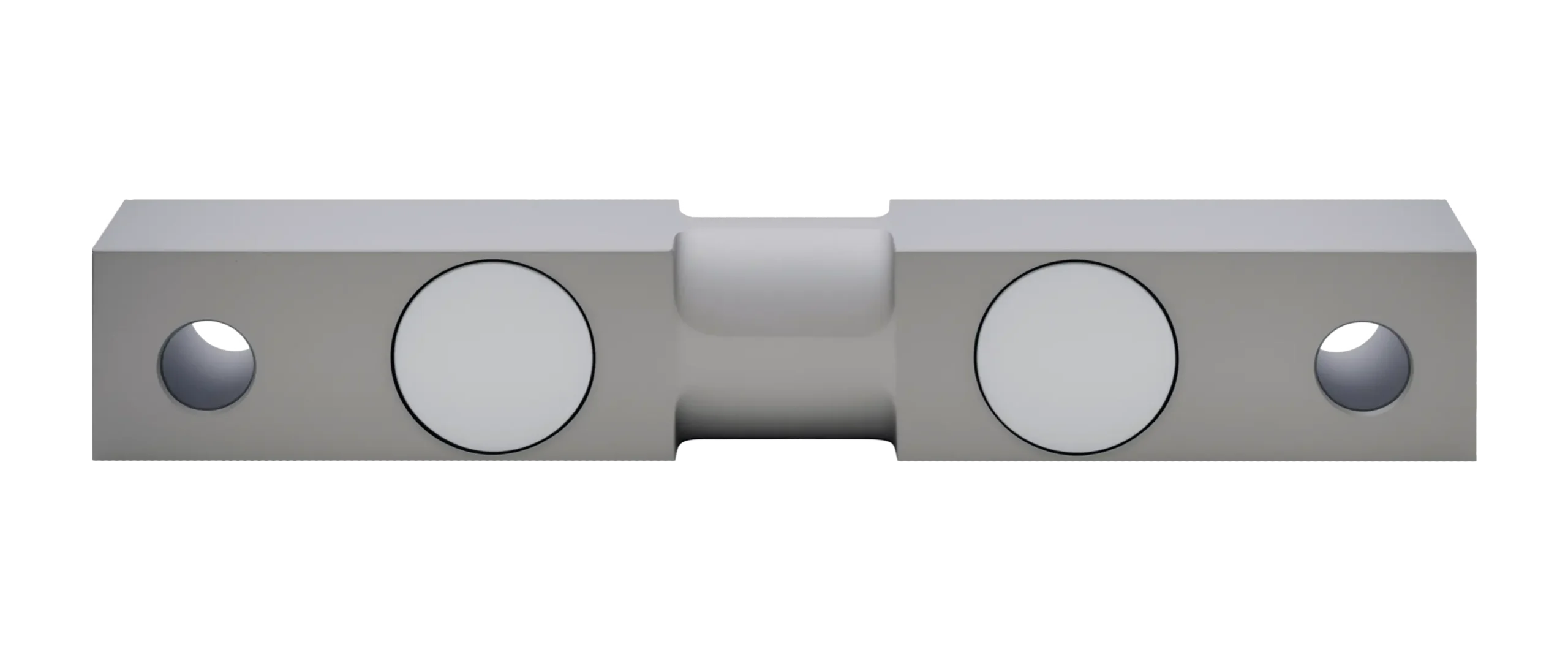
Transcell DBS double-ended beam load cell, straight-on side view showing both shear cavities and the mounting holes

Before you specify one

The questions worth asking.

How do I choose between single-ended and double-ended?

By the structure, not by the load. A single-ended beam needs one rigid mounting face and is cheaper to install, so it suits a frame that does not move much. A double-ended beam needs two supports and a centre bearing, and earns that back in capacity for the same body depth and in a structure left free to expand. If the deck is long, outdoors, or carries rolling load, the double-ended answer is the sound one.

Can I bolt one down?

Yes. The DBS bolts down at both ends through its mounting holes. Where the structure above it grows and shrinks with temperature, bring the load into the centre through a rocker pin or a link rather than a rigid joint, so that movement is not reacted through the load cell as drift that tracks the weather.

Is the DBS legal for trade?

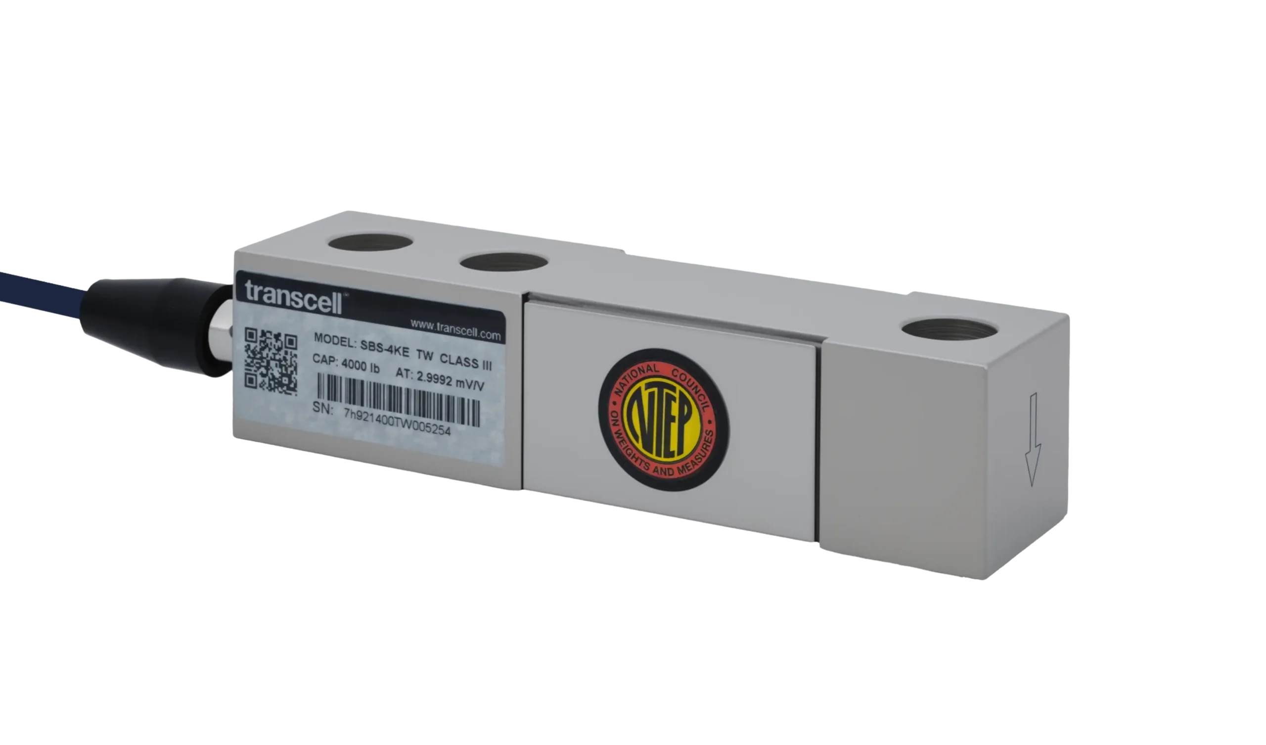
No NTEP certificate is quoted for it. Where the reading has to be a legal weight, the SBS single-ended shear beam is certified under CoC 95-146 from 1,000 through 10,000 lb. Above that range, tell us what the certification has to cover.

Can you supply a capacity or a build that is not listed?

Regularly. The series is specified from 1,000 lb, so capacities below and between the nine stocked ones are built to order, and cable length outside the standard 6 m, 10 m and 20 m is routine. The DBS is also supplied with its mounting hardware as a weighing module kit.

We Make Your Challenge Our Business

Tell us what it has to do and we’ll tell you what it takes.

Contact Us