How they work
Bend a beam. Read the surface.
A bending beam load cell is a cantilever with strain gauges on its top and bottom faces. Bolt one end down, push down on the other, and the two faces do opposite things, which is what a Wheatstone bridge is built to measure.
Tension on top, compression underneath
Load the free end of a fixed beam and it curves. Material above the neutral axis is stretched, material below it is squeezed, and the plane through the middle does neither. The further from that plane, the larger the strain, which is why the gauges sit on the outer surfaces rather than buried in the section.
Two gauges go on the top in tension, two on the bottom in compression. Wired as a full bridge all four are active and push the output the same way, so the signal is four times what one gauge gives. Anything affecting all four equally (temperature, excitation drift, common-mode noise on the cable) moves the arms together and cancels.
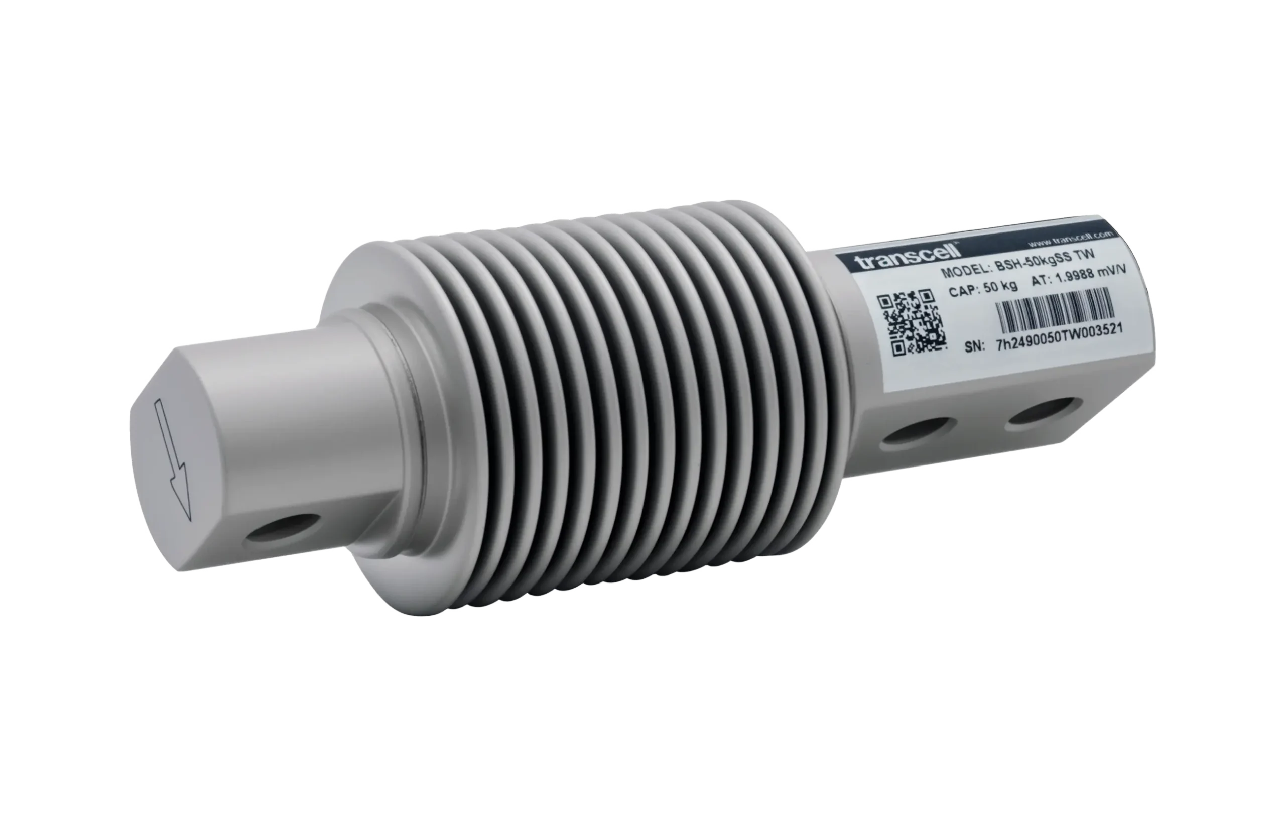
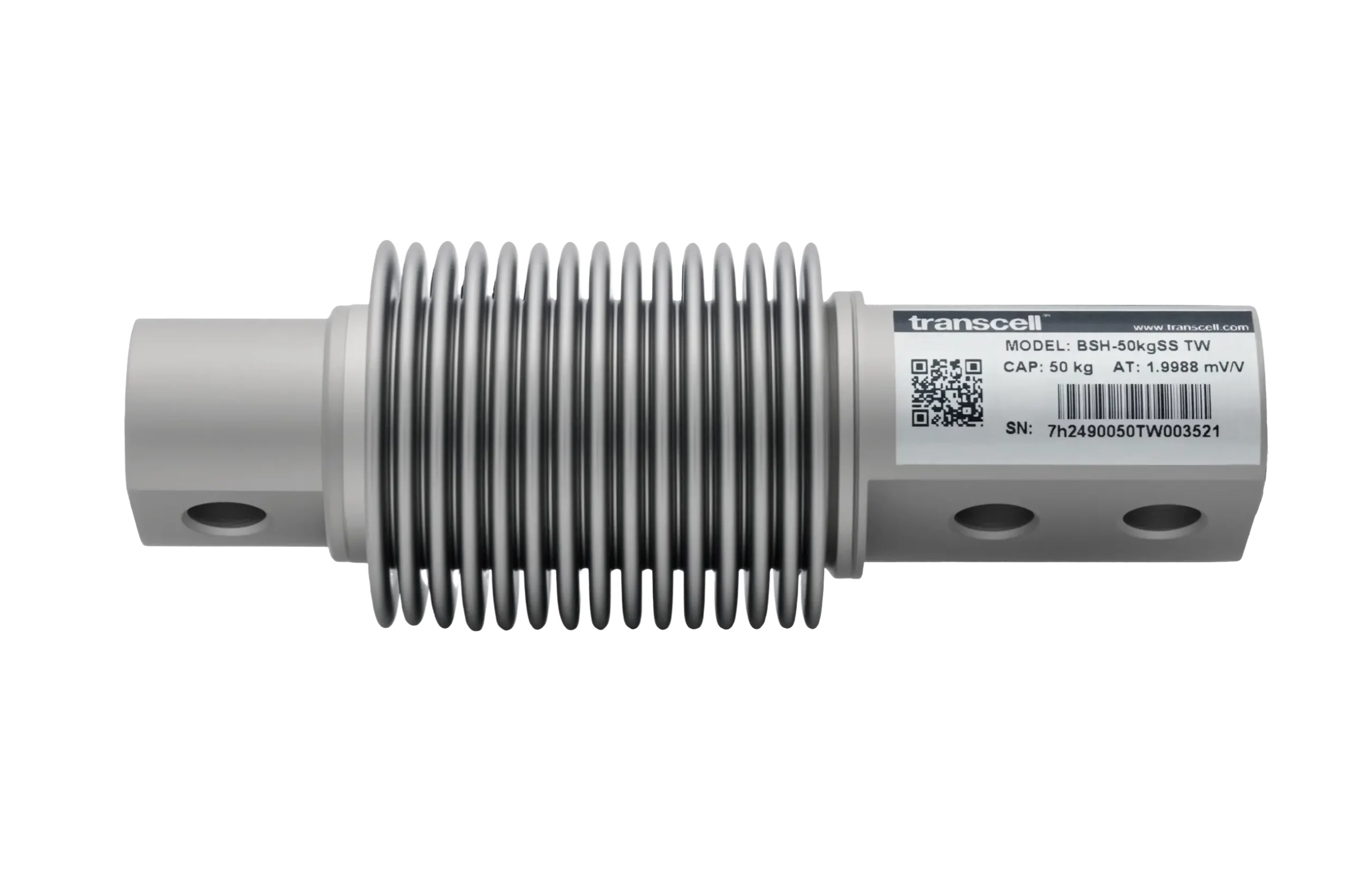
The BSH is machined so the sensing section is thinned and the rest of the body is not, concentrating strain where the gauges sit. The result is 2.0 mV/V ±0.1% at rated load, with nonlinearity, hysteresis and repeatability each held to ±0.03% of rated output.
Go deeper
Bending against shear, and what it costs you
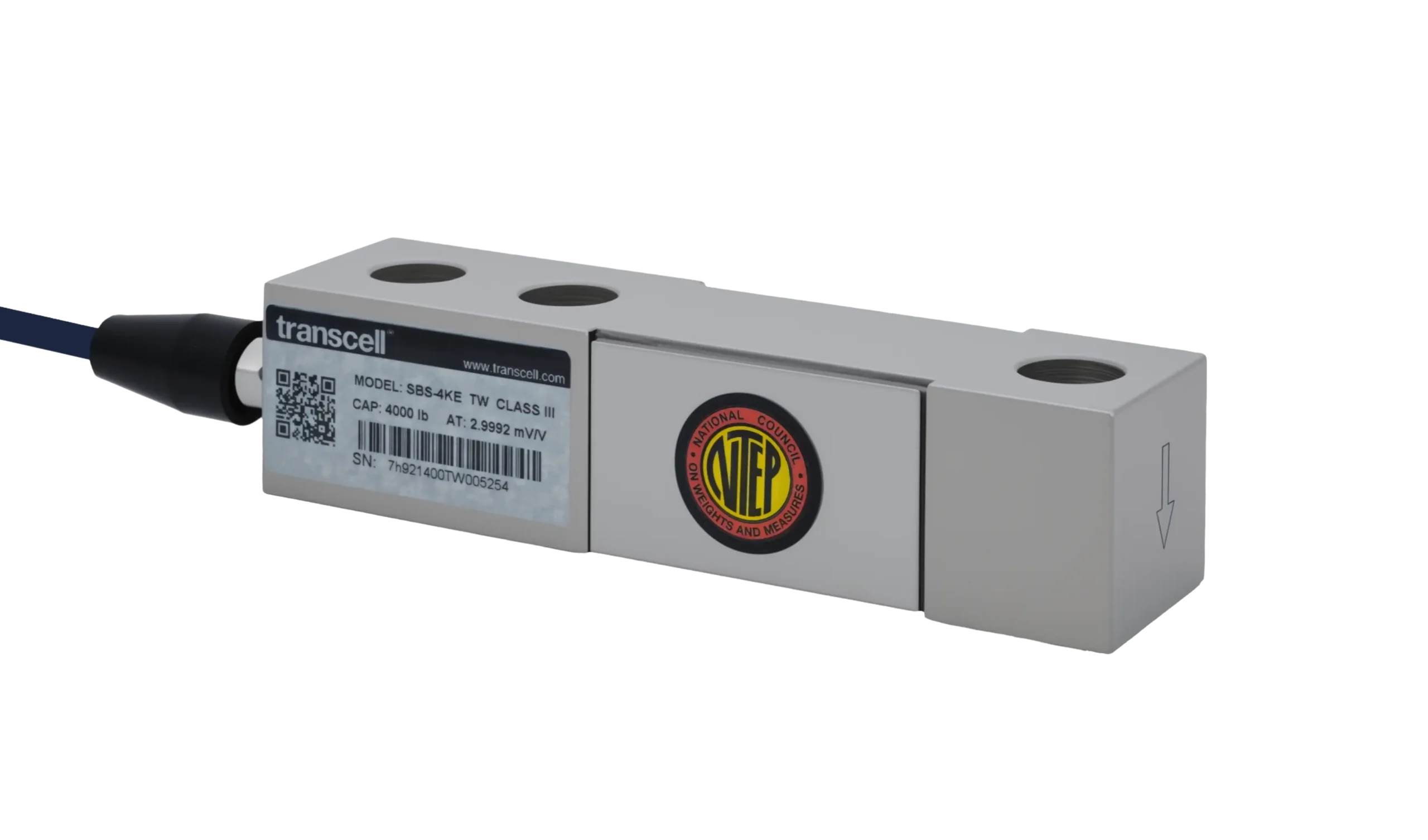
Bending moment is force multiplied by the distance from the load to the sensing section, so a bending beam's output depends on where along the beam the load lands. A shear beam is machined with a thin web and gauges at 45° to read shear force instead, and shear force between support and load does not vary with distance.
That is the trade. A load introduced further out than it sat at calibration reads high, and no span adjustment fixes a loading point that wanders in service. It is the failure mode to design out at the mount.
What you get in exchange is strain. Bending puts far more strain on an outer surface than shear puts on a web, so a bending beam reaches full output from a smaller, cheaper section. At 50 kg a shear web sized for the same output would be thin enough to be fragile. That is why bending dominates the low-capacity end and shear takes over higher up.
Bending beam against single point
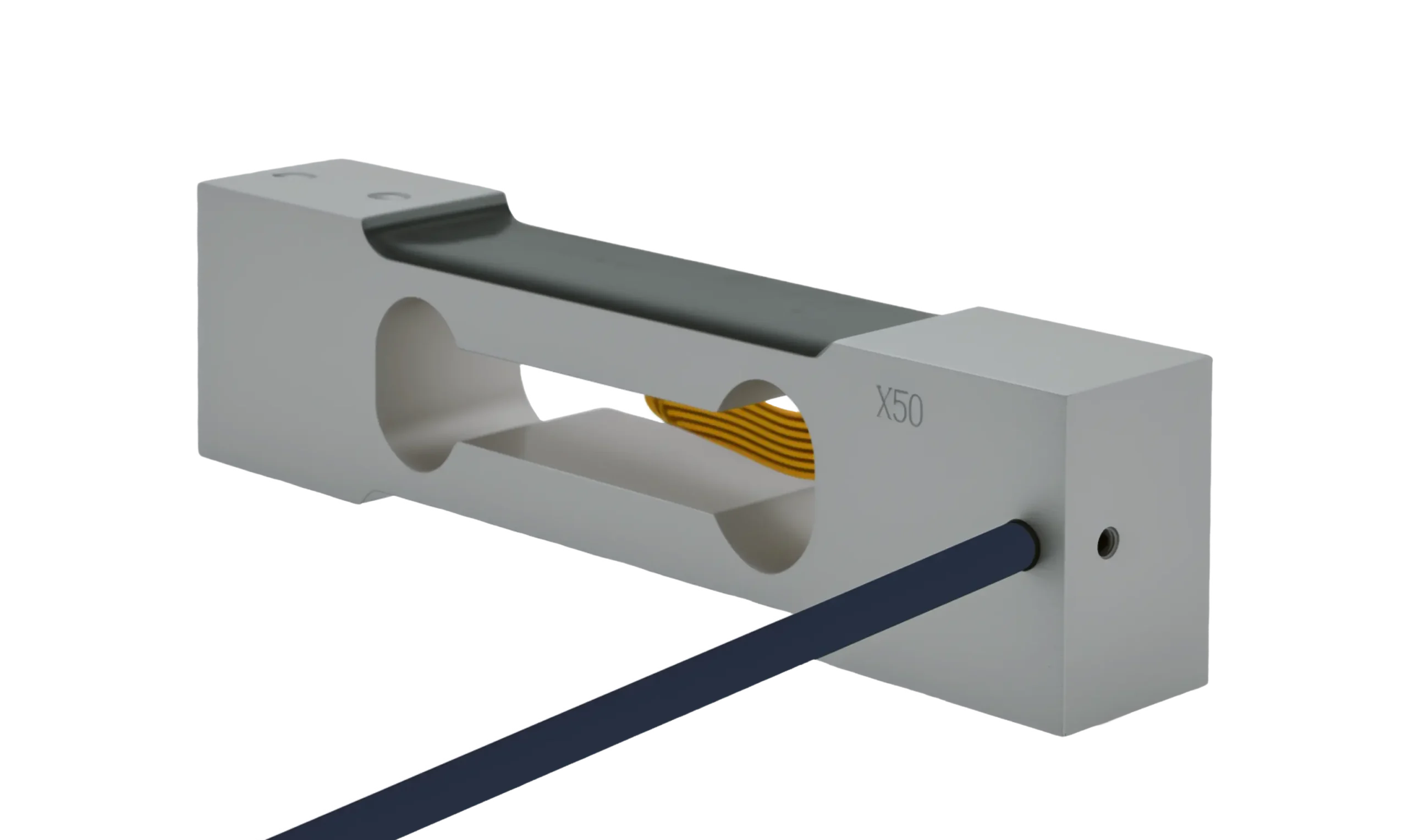
A single point is also loaded on a free end, but it is cut as a parallelogram whose parallel flexures turn an off-centre load into rotation of the platform rather than strain at the gauges, then trimmed by hand until every corner of a rated deck agrees with the centre.
A plain bending beam has none of that: one flexural axis, no corner compensation, so it wants the load delivered to a defined point. Put a bare bending beam under the middle of a platform and corner readings disagree, because they genuinely are different bending moments.
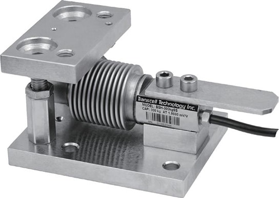
So the choice is rarely accuracy: the single point families and the BSH both hold ±0.03%. It is environment and load introduction. Aluminium single points are cheaper and self-compensating; the BSH is stainless with a welded seal and survives what dissolves them.
Why the bridge is not a balanced 350 ohm square
Put an ohmmeter across a BSH and the pairs do not match: input impedance 387 ohm ±20 ohm, output impedance 350 ohm ±5 ohm. That is not a fault. The datasheet specifies the two sides differently, and both figures are normal.
The compensation holds ≤0.002% of applied output per °C on span and the same of rated output per °C on zero, across a compensated band of -10°C to +40°C. The body is safe to +70°C, where it keeps working and stops being compensated. Both impedances are also the field diagnostic: a pair well off either figure is damage inside the body, not a wiring fault.