
Digital Weight Transmitters
Weight transmitters for PLCs and industrial networks.
Designed, built and calibrated in-house.
Free shipping across the USA.

A transmitter is one link in the chain. One catalog, one order.
The LCT-2 needs four load cells, six-wire shielded cable and a 24 V DC supply before it can send anything. All of it comes off the same shelf, on the same order.
Load Cells
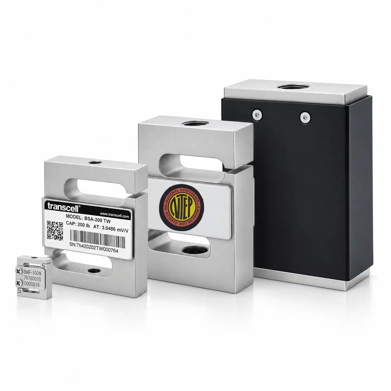
The LCT-2 reads four analog 350-ohm bridges. Twelve families of load cells, designed, built and calibrated in the same building as the transmitter.
View products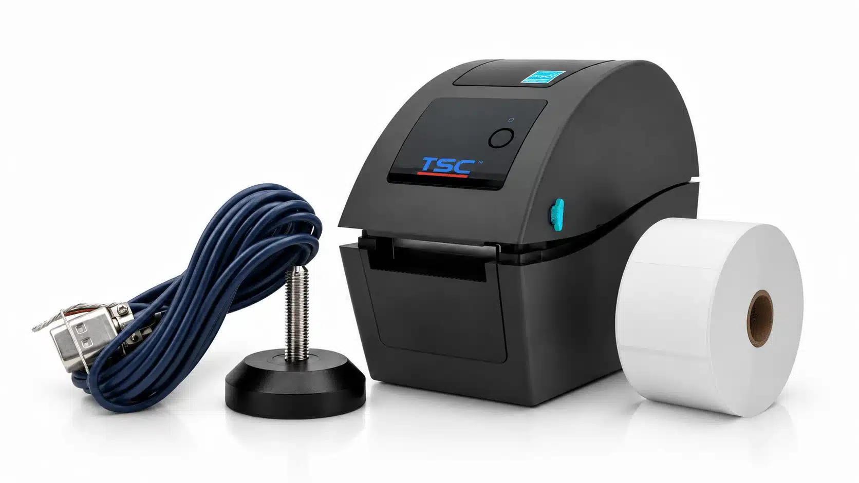
Cables & Accessories
Six-conductor shielded cable to carry excitation, sense and signal into each terminal block. Cable is where most noise complaints actually start.
View products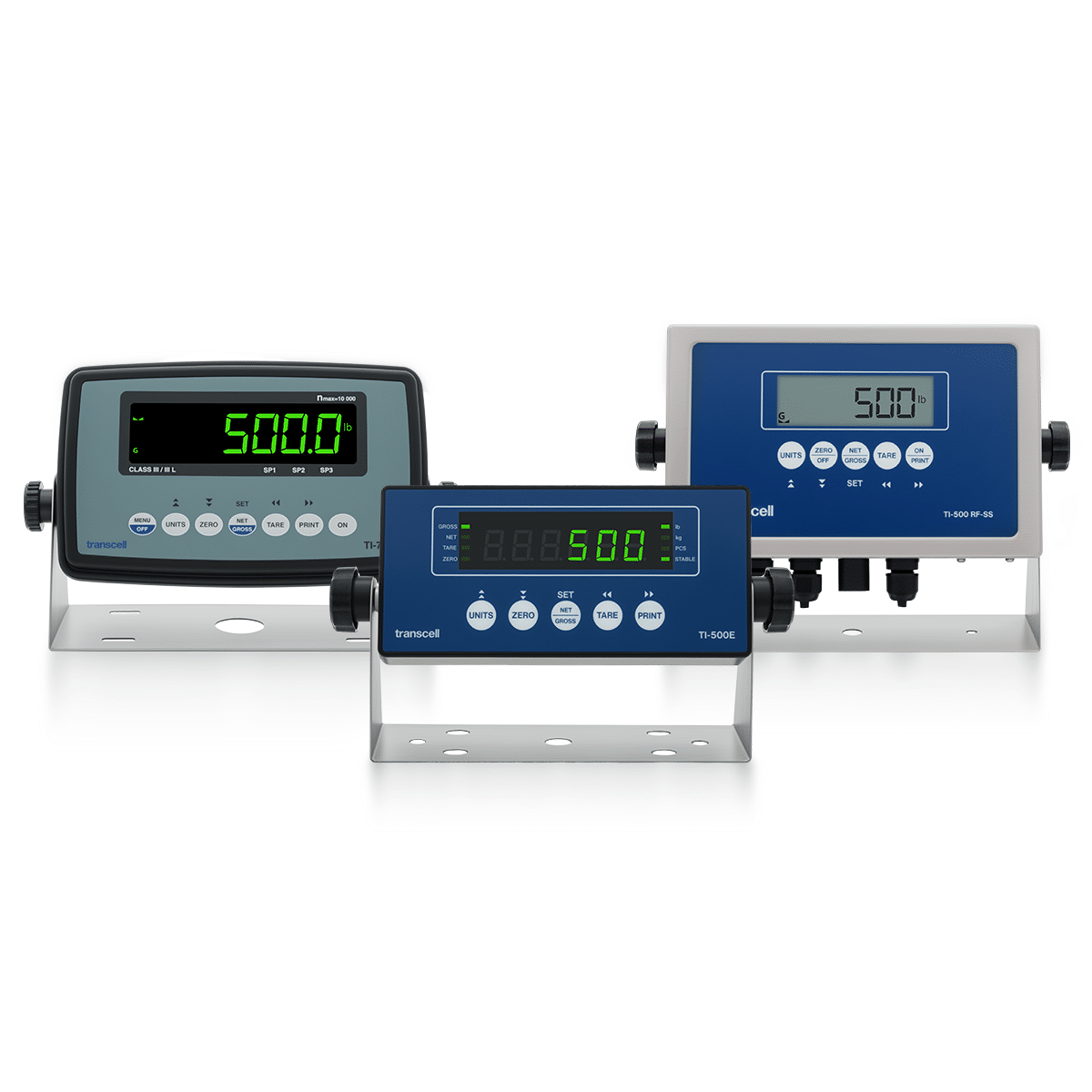
Digital Indicators
When a person has to read the number as well as a controller, or when the reading has to be legal for trade, the answer is an NTEP-certified indicator.
View productsWhy Transcell. Ordered like a store, backed like a partner.
Free 2-day shipping
Free 2-day shipping on every USA order, Alaska and Hawaii included, no minimum. Floor scales ship free by ground, continental USA only.
Ships worldwide
International orders ship at FedEx live rates: what FedEx charges is what you pay.
Warranty backed
Every product carries a manufacturer warranty. If something goes wrong, you deal with the people who built it.
Custom when you need it
Can't find the perfect fit? We build custom load cells and custom electronics for OEMs every day.
Digital weight transmitter reference
How to specify a digital weight transmitter: whether a transmitter is the right instrument at all, which protocol the controller already speaks, how the load cells wire in, whether you need test weights, and what happens when a load cell fails. Below, each of those in turn, how the LCT-2 turns four bridge signals into a network value, the full specification, every protocol option, the terminal and commissioning detail, and the vocabulary used on the datasheet.
Which weight transmitter do you need? Five questions, in order.
A transmitter is chosen differently from an indicator. There is no display to compare and no housing to match to a room. What decides it is what reads the data, what protocol that thing speaks, how many load cells are in front of it and how much you want to know about each one.
Is a transmitter the right instrument?
Three different instruments sit between a load cell and the rest of a system, and they are chosen for three different reasons.
A digital indicator is built for a person. It has a display, a keypad, tare, net and gross, a print key and, where it matters, an NTEP certificate. If a human has to read the weight, or the weight is the basis of a sale, that is the instrument. Those are on the digital indicators page.
A signal conditioner is built for a wire. It takes the few millivolts a load cell produces and turns them into something that survives a long run and lands on a standard input: 0–10 V, or a 4–20 mA loop. It does not know what a weight is, and it never applies a calibration. Those live under signal conditioners.
A digital weight transmitter is built for a controller. It digitises the bridge signals where they arrive, applies the calibration itself, and hands the PLC a finished weight value over a network the PLC already speaks. Nothing analog leaves the box, so there is no analog card to scale, no 4–20 mA range to map, and no drift between the box and the input card. The LCT-2 does one more thing the other two cannot: because each load cell has its own converter, the host can ask about the load cells one at a time.
What protocol does the controller speak?
Order the protocol the controller already runs. Nothing about the measurement changes between them: the same four converters, the same calibration and the same diagnostics sit behind every option. Only the interface board differs.
RS-485 with Modbus RTU and Modbus ASCII is standard and costs nothing extra. It is half duplex, it multi-drops, and it is the cheapest reliable way to get weight into almost any controller built in the last thirty years. RTU is the compact binary form and is what you want for speed; ASCII is readable on a terminal, which makes it the easier one to commission by hand. Note that on the EtherNet/IP build the RS-485 port is fixed at 19200 baud, 8 data bits, even parity, 1 stop bit, no flow control, because that port is also the configuration and calibration channel.
Modbus TCP/IP adds $200 and puts the same Modbus messages inside a TCP wrapper on an RJ-45 port. If your SCADA package or PLC already polls Modbus over Ethernet, this is the smallest change to the rest of the system.
EtherNet/IP adds $440 and is the usual answer for Rockwell and Allen-Bradley hardware. It presents as a generic module with a Class 1 implicit I/O connection, so the weight arrives in the controller tag database on every scan rather than being polled by ladder logic.
PROFIBUS, PROFINET, CANopen and DeviceNet are among the twenty industrial network protocols the platform supports and are quoted per order. If the plant standard is Siemens or an existing device-level bus, tell us the protocol and we will confirm the build before you order.
How many load cells, and how do they wire in?
An indicator wires its load cells in parallel and the published count is really an excitation budget: add load cells, divide the bridge resistance, and eventually the supply runs out. The LCT-2 is not built that way. It has four separate terminal blocks and four separate A/D channels, so four is a hard limit and each load cell is measured on its own.
Each block takes a full six-wire connection: +EXC, −EXC, +SE, −SE, +SIG and −SIG. The sense pair is not optional decoration here. It lets the transmitter measure the excitation voltage as it actually arrives at the load cell rather than as it left the terminal, which is what cancels the voltage drop in a long cable run. Excitation is +3.3 V DC and the input range is ±3.125 mV/V, which covers any standard 2 mV/V or 3 mV/V load cell.
One installation detail catches people out often enough to be worth stating twice: if you connect fewer than four load cells, the +SIG and −SIG terminals on every unused input must be shunted with a jumper wire. An open input is not read as absent, it is read as a fault.
The 24 V DC supply is external and not included, drawing 0.5 A. There are two sets of power terminals rather than one, so several transmitters can be daisy chained onto a single 24 V bus instead of each needing its own supply.
Do you need test weights to calibrate it?
Calibrating a large installation conventionally means getting certified test weights to it, or substituting material and weighing that instead. Both are slow, and on anything elevated or enclosed both are expensive.
The LCT-2 offers a calibration-free mode that scales the transmitter directly to the mV/V calibration data printed on each load cell's certificate. Because every load cell is on its own channel, each one can be scaled with its own figure rather than with an average across the set. For a great many process installations that removes test weights from the commissioning plan entirely.
When weights are available, the transmitter also supports single-point span, multi-point span for installations where mid-range linearity matters, and digital corner balancing, which trims the load cells so the same load reads the same regardless of where it sits. On an analog junction box corner trimming is done with potentiometers, by hand, in the box. Here it is a number, set remotely, and it does not drift.
Configuration, calibration and diagnostics are all done over the RS-485 port, so a commissioned unit can be re-scaled without opening the enclosure.
What happens when a load cell fails?
This is the argument for a transmitter over a junction box, and it is worth being precise about. A summing junction box adds four analog signals into one before any instrument sees them. When one load cell drifts, corrodes or loses a leg, what reaches the indicator is a single number that is quietly wrong. Nothing in the system knows which load cell caused it, and often nothing knows anything is wrong at all until a product weight is out of tolerance.
The LCT-2 converts each load cell separately and runs real-time diagnostics on the system, so a fault is detected as it happens and can be raised as an alarm in the controller rather than found later. The host can read the A/D counts and the weight value for each individual load cell as well as the compound weight, which turns a fault into a specific instruction: replace the load cell on channel three.
It also offers dead load cell emulation, which substitutes a value for the failed channel so the system keeps producing a usable reading until the load cell can be changed. That is a deliberate trade: the reading is an approximation while emulation is active and should not be treated as a measurement of record. What it buys is the choice of when to stop, rather than stopping now.
The same architecture helps before anything fails. Because conversion happens at the transmitter, the long analog homerun cable that usually sits between a junction box and an instrument is removed from the signal path, and with it most of the noise and voltage-drop error that run picks up.
From four bridge signals to a network value. What the transmitter actually does.
A load cell produces nothing on its own. The transmitter powers all four bridges, reads each one on its own converter, applies the scaling and corner trim, and hands the result to whatever is on the network.
01
Excitation out
The transmitter supplies a stable +3.3 V DC to four 350-ohm bridges, with a sense pair on each so cable drop is measured, not assumed.
02
Four signals back
Each load cell returns its own few millivolts. Input range is ±3.125 mV/V, with sensitivity of 0.3 µV/grad minimum.
03
Four converters
One 24-bit A/D per load cell, adjustable from 4.7 Hz to 4800 Hz. No summing happens before this point.
04
Scale, trim, filter
mV/V or span calibration per channel, digital corner balancing across them, then filtering. Set remotely over RS-485.
05
Onto the network
Compound weight, per-channel weight, raw counts and status, over Modbus RTU, Modbus TCP/IP or EtherNet/IP.
Sampling rate is a trade, not a score. Fast conversion catches a filling event or an impact; slow conversion gives a steadier number for a controller that only reads it once a second. The 24-bit converter resolves far more than any installation can usefully display, and the useful figure is the analog sensitivity per graduation rather than the bit count.
Which configuration to order. Decided by what is on the other end.
The last two rows deliberately point out of this category: a transmitter is the wrong instrument for both.
| If the other end is | Order | Why |
|---|---|---|
| An Allen-Bradley or Rockwell controller | LCT-2 with EtherNet/IP +$440 | Presents as a generic module on a Class 1 implicit connection, so the weight lands in the tag database every scan instead of being polled from ladder logic. |
| A PLC or SCADA already polling Modbus over Ethernet | LCT-2 with Modbus TCP/IP +$200 | The same Modbus messages inside a TCP wrapper on an RJ-45 port. The smallest change to a system that already has a Modbus driver. |
| An existing RS-485 Modbus network | LCT-2, base configuration standard | Half-duplex RS-485 multi-drops onto the segment you already have. Modbus RTU for throughput, Modbus ASCII when you want to read the traffic on a terminal. |
| A Siemens or fieldbus plant standard | LCT-2, quoted build PROFIBUS, PROFINET | Among the twenty industrial network protocols the platform supports. Name the protocol and we confirm the build before the order is placed. |
| A machine-level device bus | LCT-2, quoted build CANopen, DeviceNet | Same measurement platform, different interface board. Quoted per order because the hardware is fitted to the build. |
| Several transmitters on one panel | LCT-2 × the number of scales | Two sets of power terminals per unit, so they daisy chain onto a single 24 V DC bus rather than each carrying its own supply. |
| A person reading a display | A digital indicator | A transmitter has no display and no keypad. If the weight has to be read, tared or printed at the scale, or has to be legal for trade, it is the wrong instrument. |
| An analog input card wanting 4–20 mA | A signal conditioner | Nothing analog leaves the LCT-2. If the controller only has analog inputs available, condition the signal instead and skip the network entirely. |
The full specification. And what each line means in practice.
Every figure below is from the LCT-2 datasheet, version 2.15.
| Specification | LCT-2 | What it means for the installation |
|---|---|---|
| Load cell excitation | +3.3 V DC | Lower than the 5 to 10 V an indicator supplies, which is possible because conversion happens at the transmitter rather than at the end of a long analog run. |
| Load cell current | Four 350 Ω load cells | A hard channel count, not a parallel excitation budget. One terminal block and one converter per load cell. |
| Analog signal input range | ±3.125 mV/V max | Covers any standard 2 mV/V or 3 mV/V strain-gauge load cell, from any manufacturer. |
| Analog sensitivity | 0.3 µV/grad min 0.6 µV/grad rec. | The real resolution figure. Divide the load cell's full-scale output by your graduation size and check it clears 0.6 µV for a comfortable design. |
| A/D resolution | 24 bits | Internal resolution, far finer than anything a controller needs to act on. Headroom, not displayable precision. |
| A/D conversion rate | 4.7 Hz to 4800 Hz | Adjustable. Fast for filling, dosing and impact capture; slow for a steady number on a slowly changing load. |
| Number of ADC channels | Four | Each load cell is measured independently, which is what makes per-channel diagnostics and mV/V scaling per load cell possible. |
| Serial port | Half duplex RS-485 | Standard on every unit, and also the configuration, calibration and diagnostics channel. Multi-drops onto an existing segment. |
| Remote functions | Zero, stream start/stop, demand data, ADC counts | The host can zero the system, switch between streamed and on-demand data, and read raw counts for troubleshooting. |
| Power requirements | 24 V DC, 0.5 A | External supply, not included. Two sets of terminals so units daisy chain onto one bus. |
| Operating temperature | −10 °C to 40 °C (−14 °F to 104 °F) | An in-plant range. An unheated dock in winter or an uncooled roof space in summer sits outside it, so mount the transmitter in conditioned space and run cable to the load cells. |
| Dimensions | 9.0″ × 7.1″ × 2.1″ 228 × 181 × 53 mm | Mounting tabs for a wall or a panel, vertically or horizontally. Allow room on one face to lift the cover for the terminal blocks. |
| Warranty | 12 months limited | Against manufacturing defects in material and workmanship under normal use, factory-direct. |
Specifications are from the published LCT-2 datasheet and are subject to change without notice. The full document is on the product page under Data Sheets, along with the quick start guides for the Modbus TCP/IP and EtherNet/IP builds.
Every protocol option. One measurement platform, four ways out.
The interface board is the only thing that changes between these. The converters, the calibration and the diagnostics are identical.
Standard
RS-485, Modbus RTU & ASCII
Half duplex, multi-drop, on every unit at no extra cost. RTU is the compact binary form; ASCII is readable on a terminal, which makes commissioning by hand easier.
Use for existing serial networks, panel-local runs, retrofits.
+$200
Modbus TCP/IP
The same Modbus messages inside a TCP wrapper, over an RJ-45 port on an embedded device server. Addressing is set once, over the serial console, then saved.
Use for SCADA packages and PLCs that already poll Modbus over Ethernet.
+$440
EtherNet/IP
Presents as an EtherNet/IP slave over a Class 1 implicit I/O connection, with the IP address assigned by BOOTP. Data is little endian, which catches people out once.
Use for Rockwell and Allen-Bradley controllers, ControlLogix tag integration.
Quoted
PROFIBUS, PROFINET, CANopen, DeviceNet
Four of the twenty industrial network protocols the platform supports. Fitted to the build rather than added later, so the protocol is named at the time of order.
Use for Siemens plant standards and existing device-level buses.
On the EtherNet/IP build, three data layouts are available on the same input assembly: raw counts for all four load cells (18 bytes), counts plus per-channel weight (34 bytes), or counts, per-channel weight, compound weight and status (42 bytes). The wider two have to be enabled over the RS-485 port before the controller will see them.
Wiring and commissioning. What the quick start guide covers.
The transmitter mounts by its tabs to a wall or panel, in either orientation. The cover comes off with four screws, and everything below is inside it.
| Terminal | Function | Notes |
|---|---|---|
| +EXC / −EXC | Excitation | The +3.3 V DC supply to the bridge. Present on all four blocks, LC1 through LC4. |
| +SE / −SE | Sense | Measures the excitation as it arrives at the load cell, which cancels the voltage drop in a long cable run. Use six-conductor shielded cable to keep the pair. |
| +SIG / −SIG | Signal | The millivolt output of the bridge. On every unused input these two must be shunted with a jumper wire, or the channel reads as a fault. |
| +24V / 0V / EARTH | Power | External 24 V DC at 0.5 A, not included. Two sets are provided so several transmitters daisy chain onto one bus. |
| RJ-45 | Ethernet | On the Modbus TCP/IP and EtherNet/IP builds only, from the device server module on the JR1 socket. |
Disconnect power before removing the cover. Strip each wire back 10 mm, tin it and crimp it onto a stud before inserting it into the spring-loaded terminal. On the EtherNet/IP build the RS-485 port is fixed at 19200 baud, 8 data bits, even parity, 1 stop bit, no flow control, because it doubles as the configuration channel. Addressing is assigned by BOOTP on the EtherNet/IP build and through the serial setup menu on the Modbus TCP/IP build, and it is saved in the device server rather than set by switches. Full step-by-step instructions are in the quick start guides on the product page.
Datasheet terms, in plain language. What they mean when you're specifying.
Show all 28 terms
- Digital weight transmitter
- An instrument that digitises load cell signals, applies the calibration itself and sends a finished weight value over an industrial network. No display, no analog output.
- Intelligent junction box
- The same enclosure doing the junction box's job, but converting each load cell separately instead of summing them into one analog signal.
- Homerun cable
- The long analog run from a junction box back to an instrument. A transmitter removes it from the signal path, and with it most of the noise it picks up.
- Excitation
- The stable voltage supplied to the load cell bridge, +3.3 V DC here.
- Sense lines
- The extra pair in six-wire cabling that reports the excitation voltage as it arrives at the load cell, correcting for cable drop.
- mV/V
- A load cell's rated output per volt of excitation. A 2 mV/V load cell at full load returns 2 mV for every volt applied.
- Input range
- The largest bridge signal the transmitter can read, ±3.125 mV/V here, which covers standard 2 and 3 mV/V load cells.
- Graduation (grad)
- One displayed or reported increment of weight. The size you choose sets how much signal each step has to be worth.
- µV/grad
- Microvolts of signal per graduation. The practical resolution figure: 0.3 minimum, 0.6 recommended.
- A/D resolution
- The converter's own resolution, 24 bits here. Internal headroom rather than usable displayed precision.
- Conversion rate
- Readings per second, adjustable from 4.7 to 4800 Hz. Fast catches transients, slow reads steadier.
- mV/V calibration
- Scaling the transmitter from the calibration certificate that came with each load cell, with no test weights and no material substitution.
- Single-point span
- Calibrating with one known load, which sets the scale factor between millivolts and weight.
- Multi-point span
- Adding calibration points between zero and full scale, for installations where mid-range linearity matters.
- Digital corner balancing
- Trimming the four load cells so the same load reads the same wherever it sits. Done as a number here, not with potentiometers.
- Compound weight
- The summed weight across all four channels, calculated after each load cell is individually scaled.
- Dead load cell emulation
- Substituting a value for a failed channel so the system keeps producing a usable reading until the load cell is replaced.
- Real-time diagnostics
- Continuous fault detection across the system, so a failure is raised as it happens rather than found in an out-of-tolerance product.
- Half duplex RS-485
- A two-wire differential serial bus where one device talks at a time. Multi-drops many devices on one pair, over long runs.
- Modbus RTU
- The compact binary form of Modbus over serial. The default and the fastest of the serial options.
- Modbus ASCII
- The human-readable form of the same protocol. Slower, but you can watch the traffic on a terminal while commissioning.
- Modbus TCP/IP
- Modbus messages wrapped in TCP and sent over Ethernet instead of serial lines.
- EtherNet/IP
- An application-layer protocol over standard Ethernet, common on Rockwell and Allen-Bradley hardware.
- Assembly instance
- The numbered data block an EtherNet/IP device exchanges with a controller. Input, output and configuration each have one.
- Class 1 implicit connection
- An EtherNet/IP I/O connection that updates the controller's tags cyclically, rather than being polled by logic.
- Little endian
- Byte order with the least significant byte first. The LCT-2 uses it, and it is the most common cause of a value that looks like nonsense on first connection.
- Device server
- The embedded Ethernet module inside the transmitter that carries the IP address and bridges the serial data onto the network.
- BOOTP
- Bootstrap Protocol, used to hand an IP address to the EtherNet/IP build the first time it joins a network.
Transmitters, answered.
What is a digital weight transmitter, and how is it different from an indicator?
An indicator is built for a person: a display, a keypad, tare, print and, where it matters, an NTEP certificate. A digital weight transmitter is built for a controller. It digitises the load cell signals where they arrive, applies the calibration itself and puts a finished weight value on an industrial network, with no display in the signal path. The LCT-2 also replaces the analog junction box, because it reads each of the four load cells on its own converter instead of summing them into one analog signal.
Which protocol should I order?
The one the controller already speaks. RS-485 with Modbus RTU and Modbus ASCII is standard on every LCT-2 and costs nothing extra. Modbus TCP/IP adds an Ethernet interface for $200, and EtherNet/IP adds one for $440, which is the usual answer for Rockwell and Allen-Bradley hardware. PROFIBUS, PROFINET, CANopen and DeviceNet are among the twenty industrial network protocols supported and are quoted per order. Nothing about the measurement changes between them.
How many load cells does the LCT-2 handle?
Four 350-ohm load cells, one per A/D channel, at +3.3 V DC excitation. Unlike an indicator, that is a hard channel count rather than an excitation budget: each load cell gets its own six-wire terminal block and its own converter. If you connect fewer than four, the +SIG and −SIG terminals on every unused input must be shunted with a jumper wire, or that channel reads as a fault.
Do I need test weights to calibrate it?
Not necessarily. The LCT-2 has a calibration-free mode that scales it to the mV/V calibration data printed on each load cell's certificate, which can remove test weights and material substitution from commissioning entirely. When weights are available it also supports single-point span, multi-point span and digital corner balancing, all set remotely over the RS-485 port.
Can I read each load cell individually?
Yes, and that is the main reason to choose a transmitter over an analog junction box. Each load cell is converted on its own 24-bit channel, so the host can read the raw counts and the weight value for each one as well as the compound weight. A summing junction box adds the load cells together before anything can see them, so a drifting load cell stays invisible until the whole reading is wrong.
What happens if a load cell fails?
Real-time diagnostics flag the fault as it happens, and because each load cell is measured separately the fault points at a specific channel rather than at the system in general. Dead load cell emulation then substitutes a value for the failed channel so the system keeps producing a usable reading until the load cell can be replaced. Treat an emulated reading as an approximation, not as a measurement of record.
Does it work with load cells from another brand?
Yes. Any standard strain-gauge load cell with a mV/V bridge output works, as long as it is 350 ohms and its rated output falls inside the ±3.125 mV/V input range. Calibration-free scaling reads the mV/V figure from the load cell's certificate, so nothing has to be matched at the factory. Our own load cells are built and calibrated in the same building as the transmitter, which is the simplest way to keep one supplier accountable for the whole system.
Does the LCT-2 come with a power supply?
No. It runs on an external 24 V DC supply drawing 0.5 A, which is not included. There are two sets of power terminals rather than one, so several transmitters can be daisy chained onto the same 24 V bus instead of each needing its own supply.
Is the LCT-2 NTEP certified for legal-for-trade weighing?
No. The LCT-2 is a process instrument and is not sold as a legal-for-trade device. If the weight is the basis of a commercial transaction, specify an NTEP-certified digital indicator instead.
What's the lead time, and is it in stock?
The base LCT-2 ships from stock with free 2-day delivery nationwide. The Modbus TCP/IP and EtherNet/IP interfaces and the quoted fieldbus builds are fitted to the order, so they carry a lead time that is confirmed before you commit. In-stock orders usually ship the same business day.
What's the warranty, and what if it fails in service?
The LCT-2 carries a 12-month limited warranty against manufacturing defects in material and workmanship under normal use. Service and repair are handled factory-direct rather than through a third party, by the same people who built and calibrated it. To start an RMA, call (847) 419-9180 or reach us through the Contact page.
Do you offer OEM and volume pricing?
Yes. Private-label versions, custom firmware and volume terms are a core part of our business, alongside standard modifications and engineer-to-order designs. Tell us the annual quantity and the protocol and an engineer will follow up. Dealer pricing is also available on request.
We Make Your Challenge Our Business
Tell us what it has to do and we’ll tell you what it takes.