


DBSL-XS Pancake Load Cell
Compression
Designed for pushing force measurement · IP65 rated · alloy steel
Same-day shipping
In-stock orders ship the same business day · Free 2-day delivery
Manufacturer direct
Designed & supported by Transcell in Buffalo Grove, IL since 1981
2-year limited warranty
US-based technical support included · repair or replace guarantee
Product Description
DBSL-XS pancake load cell overview
The DBSL-XS is a low-profile alloy steel pancake load cell built as a replacement sensing element for OEM materials testing machines. Its flat disc body stands under 51 mm tall even at 30 t capacity, allowing it to drop into the height-restricted space beneath a test frame crosshead or platen where a taller sensor will not fit. Load is applied axially through a central threaded loading boss, and eight through-holes on the mounting flange bolt the cell directly to a machined surface, so the original machine structure does not need to be modified. A nickel-plated finish protects the alloy steel body against corrosion, and the bonded foil strain gauge element delivers ±0.03% nonlinearity with the long-term stability required for repeatable test results. Available in 5 t, 10 t, 20 t, and 30 t capacities, all rated at 3.0 mV/V with 150% safe overload and a 6 m shielded cable.
|
Capacity range
5 t
up to 30 t (300 kN)
|
Nonlinearity
±0.03%
of rated output
|
Construction
Alloy steel
nickel-plated
|
Safe overload
150%
of rated output
|
Typical applications
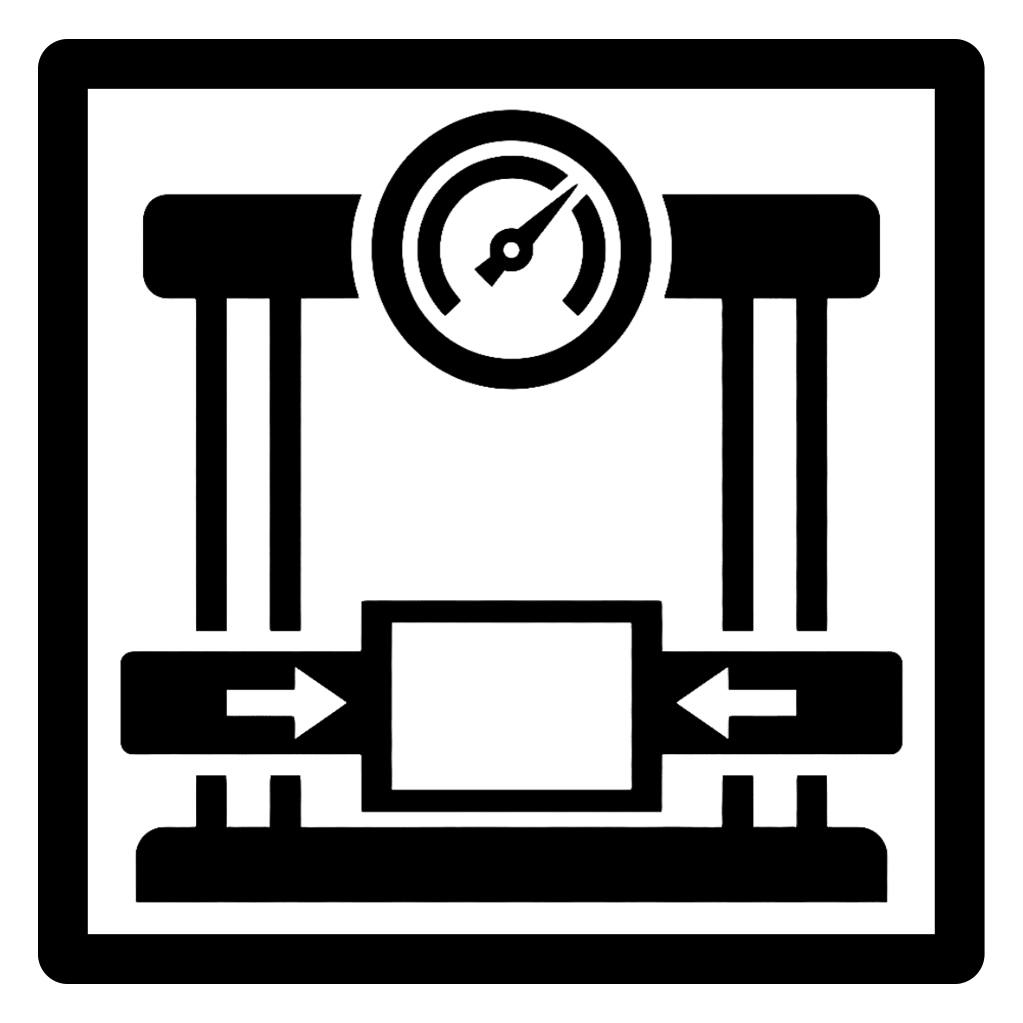
The DBSL-XS is specified primarily as a replacement load cell for OEM materials testing machines, where the low-profile pancake geometry and bolt-down flange allow it to fit the original mounting envelope.
|
|
|||||
|
|
|||||
|
|




Technical notes
|
Installation and mounting
The DBSL-XS is compression-only and must not be used in tension. Mount the cell on a flat, machined surface using all eight flange holes: ⌀11.5 mm holes on the 5 t and 10 t models, ⌀11 mm holes on the 20 t and 30 t models. Load must be applied axially through the central loading thread, M24 x 1.5 on the 5 t and 10 t models and M40 x 1.5 on the 20 t and 30 t models. Avoid side, eccentric, and off-center loading. Do not cut or splice the cable, since changing its length alters calibration. |
System integration
The DBSL-XS operates at a rated excitation of 10V DC/AC (15V max) and produces a 3.0 mV/V analog output signal. It is compatible with any standard force indicator, PLC analog input, or load cell conditioner accepting a mV/V bridge input. Bridge resistance differs by capacity group: 387 Ω input and 350 Ω output on the 5 t and 10 t models, 775 Ω input and 700 Ω output on the 20 t and 30 t models. All models ship with a 6 m (20 ft) shielded cable. |
|
Cable wiring
All DBSL-XS models ship with a 6 m (20 ft) 4-conductor shielded cable. Standard color code:
Bond the drain wire to instrument ground at one end only to avoid ground loops. |
Ordering notes
Specify the model number corresponding to the required capacity:
|
Specifications
| Model | DBSL-XS-5T | DBSL-XS-10T | DBSL-XS-20T | DBSL-XS-30T |
| Rated capacity | 5 t | 10 t | 20 t | 30 t |
| Capacity (kg) | 5,000 kg | 10,000 kg | 20,000 kg | 30,000 kg |
| Capacity (lbf) | 11 Klbf | 22 Klbf | 44 Klbf | 66 Klbf |
| Capacity (kN) | 50 kN | 100 kN | 200 kN | 300 kN |
| Loading thread | M24 × 1.5 | M40 × 1.5 | ||
| Input impedance | 387 ± 20 Ω | 775 ± 20 Ω | ||
| Output impedance | 350 ± 5 Ω | 700 ± 5 Ω | ||
| Overall diameter | ⌀154 mm (6.06 in) | ⌀141 mm (5.55 in) | ||
| Height | 45 mm (1.77 in) | 50.8 mm (2.00 in) | ||
| Bolt circle | ⌀126 mm (4.96 in) | ⌀116.8 mm (4.60 in) | ||
| Bolt holes (8×) | ⌀11.5 mm (0.45 in) | ⌀11 mm (0.43 in) | ||
| Counterbore (8×) | ⌀20 mm (0.79 in) | ⌀18 mm (0.71 in) | ||
| Loading boss diameter | ⌀50.4 mm (1.98 in) | ⌀52 mm (2.05 in) | ||
| Relief diameter | ⌀94.4 mm (3.72 in) | ⌀96.9 mm (3.81 in) | ||
| Rated output | 3.0 mV/V ±0.25% | |||
| Zero balance | ±1.0% of rated output | |||
| Nonlinearity | ±0.03% of rated output | |||
| Hysteresis | ±0.03% of rated output | |||
| Repeatability | ±0.03% of rated output | |||
| Creep (30 minutes) | ±0.03% of rated output | |||
| Safe overload | 150% of rated output | |||
| Rated excitation | 10V DC/AC (15V max) | |||
| Insulation resistance | ≥5,000 MΩ at 50V DC | |||
| Compensated temp. range | −10 to +40°C | |||
| Safe temp. range | −10 to +70°C | |||
| Temp. effect on output | ≤0.002% of applied / °C | |||
| Temp. effect on zero | ≤0.002% of rated output / °C | |||
| Material | Alloy steel, nickel plated | |||
| Element type | Bonded foil strain gauge | |||
| Direction of loading | Compression | |||
| Cable | 6 m (20 ft) · 4-conductor shielded with drain wire | |||
Dimensions / 3D Drawings
Note: You may need a software that can open/view STEP files.
-
Data Sheets
Frequently Bought Together
-
Capacity: 2 lbf - 10k lbf
 Free 2-Day Shipping
Load Cells for Chatillon DFS-R-ND and DFS II-R-ND Digital Force Gauges
Price range: $1,250.00 through $1,550.00 Select options This product has multiple variants. The options may be chosen on the product page -
Capacity: 300 to 30K lbf
 Free 2-Day Shipping
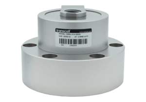
TC414 Series Base Mount Compression Load Cells
$1,400.00 Select options This product has multiple variants. The options may be chosen on the product page -
Capacity: 250 to 20K lb
 Free 2-Day Shipping
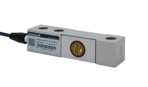
SBS Series Single Ended Shear Beam Load Cell (lb, NTEP)
Price range: $185.00 through $575.00 Select options This product has multiple variants. The options may be chosen on the product page
Ask us about our OEM and Dealer Pricing
Insights
Accurate and Reliable Force Feedback Using Load Pins
Industries
Experience to Solve Your Problems
Proven product quality and performance combine with our engineering experience to solve force measurement challenges in any industry that needs load cells and related force sensing equipment.